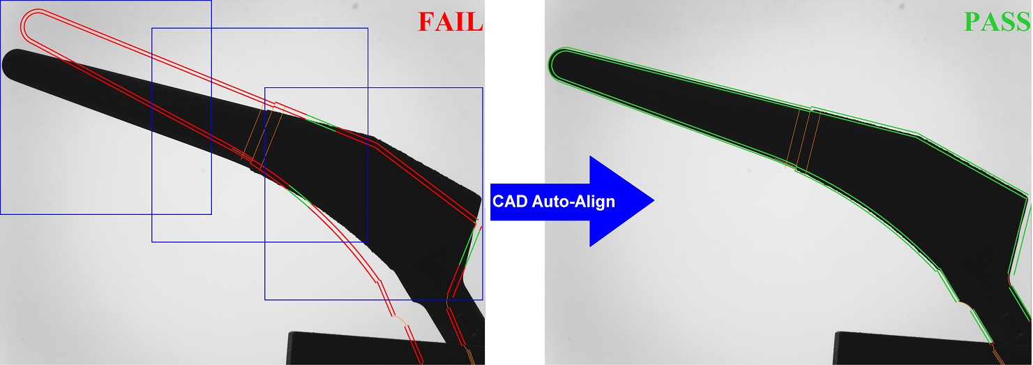
Digital Optical Comparators, News/New Developments, Press Releases, Publications, Software Feature VisionGauge® Enhanced CAD Auto-Align™ Tool Receives New US Patent (Jan. 2026) A testimonial about a new VisionGauge® High-Accuracy Inspection and Measurement System used for automated semiconductor inspection. January 20, 2026 1 MIN READ
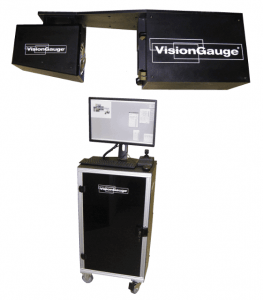
500 Series, Compact 500 Series, Digital Optical Comparators, Optical Comparators, Press Releases New Compact 500 Series VisionGauge® Digital Optical Comparator – Complete Inspection & Measurement in a Small Footprint (July 2025) The new Compact configuration of the 500 Series was developed for applications requiring full inspection functionality but where floorspace is … July 24, 2025 1 MIN READ
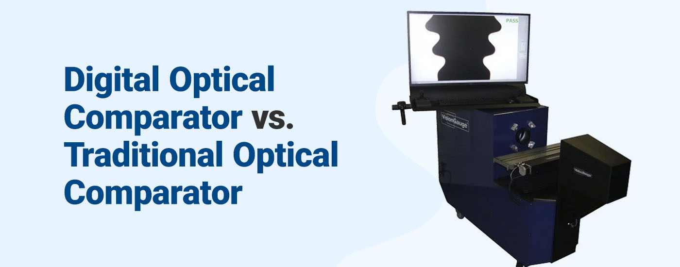
Digital Optical Comparators, Optical Comparators Digital Optical Comparator vs. Traditional Optical Comparator Wondering what the differences are between digital and traditional optical comparators? Visit our site to learn why we recommend digital … September 18, 2023 3 MIN READ
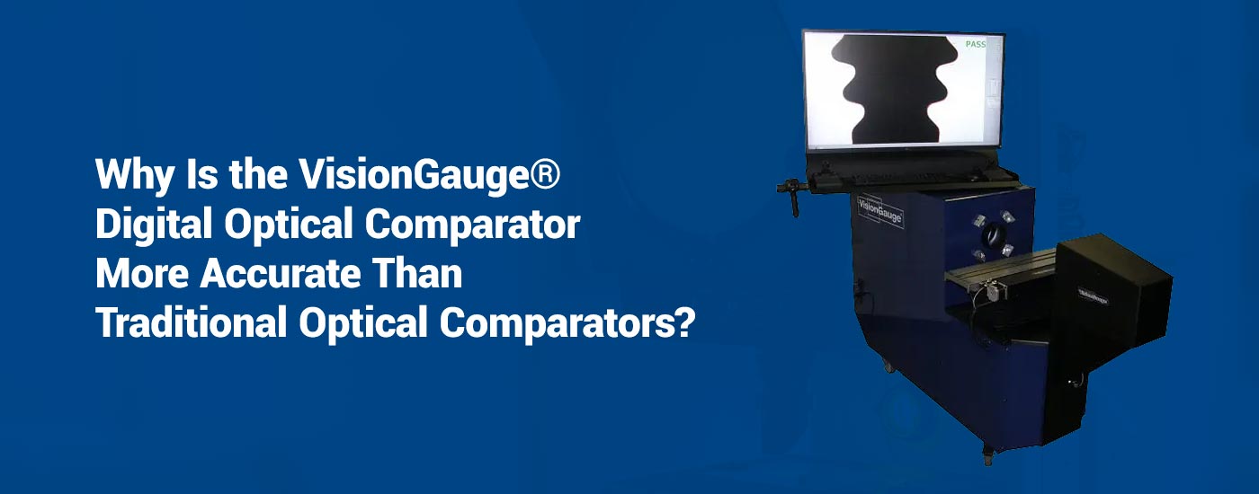
Digital Optical Comparators Digital Optical Comparator Accuracy | VisionGauge® The VisionGauge® Digital Optical Comparator offers complete measurement accuracy. Make it your go-to solution for precision in the manufacturing industry! August 9, 2022 5 MIN READ
500 Series Extended, Digital Optical Comparators, News/New Developments Announcing the Super-Extended Travel Configuration 500 Series VisionGauge® Digital Optical Comparator The Super-Extended Travel Configuration 500 Series VisionGauge® Digital Optical Comparator is designed to inspect and measure big and heavy parts. September 3, 2020 1 MIN READ
Application note, Applications, Digital Optical Comparators, News/New Developments, Software Feature, VisionGauge® Online Introducing VisionGauge®’s Patented “Tooth Checker™” tool VisionGauge's Patented Tooth Checker Tool Is The Perfect Device For All Part Inspection & Measurement Needs. Contact Our Team Today … January 8, 2020 1 MIN READ
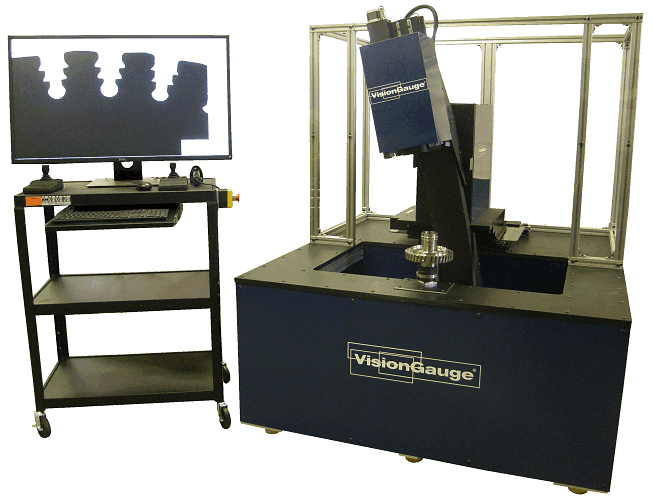
Digital Optical Comparators, Disk Inspection System, News/New Developments Announcing the VisionGauge® Disk Inspection and Measurement System VisionGauge® Disk Inspection Systems are the the ideal solution for automated, high-accuracy inspection & measurement of slots in turbine disks September 18, 2019 1 MIN READ
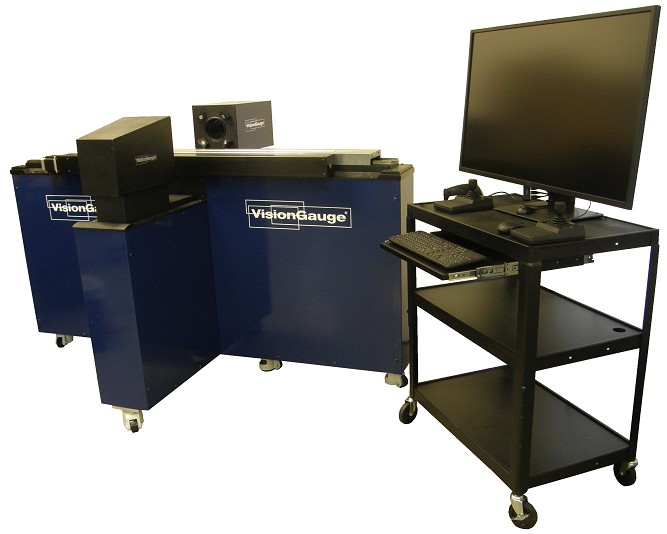
300 Series, Digital Optical Comparators, News/New Developments New 5X configuration for 300-Series VisionGauge® Digital Optical Comparator The 5x 300 Series VisionGauge Digital Optical Comparator extends the range of parts that can be checked with wider field-of-view … May 28, 2019 2 MIN READ
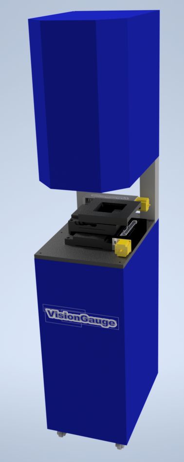
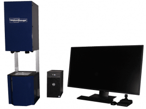
Digital Optical Comparators, News/New Developments, StandAlone Series Announcing the VisionGauge® Standalone Inspection & Measurement System The VisionGauge® Standalone Inspection & Measurement System is the perfect drop-in solution for automation applications requiring high-accuracy inspection. August 28, 2018 1 MIN READ