Our VisionGauge® products have been used across countless industries to solve a wide range of visual inspection and machine vision applications and other tasks. Below you will find a sampling of how some of our VisionGauge® products are still being applied, as well as information about our custom machine vision systems and imaging application development. Additional information about our current VisionGauge® Digital Optical Comparator applications can be found here.
Contact us with your application!
Aerospace:
- Turbine blade inspection
- Defect detection in gas turbines
Automotive:
- Automotive component verification
- Windshield urethane bead measurement (width, height & location)
- Trim measurement
- Inspection and measurement of flexible automotive components
- Engine block inspection
Biology:
- Fish scale measurement
Education:
- Distance learning & real-time image transmission
Electronics and microelectronics:
- Electronic assembly verification
- Chip serial number verification / Optical Character Recognition (OCR/OCV)
- Solder height measurement
Energy:
- Fuel cell component measurement
Glass:
- Glass cross section inspection (Straiegram)
Grains:
Industrial Gases:
- Purity verification
- Contamination detection
- Particle detection
Medical Device:
- Stent inspection
- Drug coated stent inspection
- Guide wire measurement
- Medical device assembly verification
- Optical Character Recognition and Verification for traceability
- Catheter inspection
- X-Ray detector inspection
- Dental drill inspection and measurement
- Verification of medical electronics
Micro Electro Mechanical Systems (MEMS):
Microscopy, Biology and Image Analysis:
- Photomicrography
- Particle counting and sizing
- Neurological imaging
- Cell inspection
Military and Defense:
- Military electronics: MIL spec-compliant inspection
- Hologram inspection
- Projectile inspection and measurement
- Measurement of X-Ray films
Motion Tracking / Video Capture and Motion Analysis:
- Heart valve commissure tip tracking
- Monitoring high-speed processes and equipment
- Automotive testing – crash and impact analysis
Nuclear:
- Fracture detection and measurement in radioactive materials (inside a hot cell)
Optics and Optical Manufacturing:
Orthopaedics:
- Inspection and measurement of orthopaedic implants
- Prosthesis verification and gauging
- Taper measurements
Packaging:
- Print quality verification
- Packaging verification and inspection
- Capsule integrity verification
Pharmaceutical:
- Label verification
Precision Mechanical Components and Assemblies:
- Assembly verification
- Measurement of mechanical component
Printed circuit board:
- Line and trace width measurement
- Thru-hole and via inspection and measurement
- Cross-section measurement
- Printed circuit board inner layer measurement
Probe cards:
Robots:
Semiconductor:
- Semiconductor polishing pad inspection
- Hybrid inspection
- Epoxy underfill measurement
- Semiconductor inspection
- Semiconductor defect detection
- Semiconductor line and trace width measurement
- Semiconductor feature measurement
- Epoxy measurement
- Substrate inspection
- Wafer inspection and flaw detection
Sporting Goods:
- Automated verification of baseball bat characteristics and dimensions
Tooling:
- Measurement of saw blade teeth
- Tool wear measurement
Welding:
Wire & Cable:
- Cable cross-section measurement
- Connector pin-out verification
- Connector measurement
Wire Bonding:
Custom Machine Vision Systems and Imaging Application Development
All of our standard vision systems can be configured with different optics and components to meet various requirements. However, sometimes more customization is required to achieve all of the goals of an inspection system: This type of customization is something we do especially well.
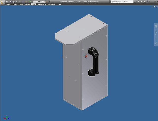
The process of developing custom machine vision systems designed to meet the requirements of a costumer’s application usually starts from a blank drawing board. Once the system goals have been identified, a group of our engineers will brainstorm ideas in order to find the most optimal solution to fulfill the customer’s needs. If system integration will be required, we may also need to understand the customer’s current processes to determine exactly how the system will fit. After a general idea of usage has been defined and some sketches are produced, the next step is to create a 3D physical model of the system for the customer’s approval.

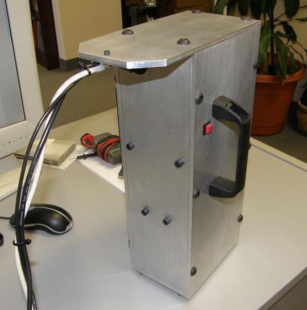
Once the 3D physical model is approved, our machinist uses CAD drawings to create the parts required for assembly in the desired materials. Meanwhile, we will continue to work on any custom enhancements to the software, if any are required. After all parts have been machined the system is assembled in-house and closely compared to the physical model to assure that the model and final product are identical.

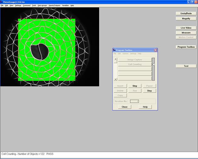
Finally, the system is thoroughly tested to ensure that it effectively solves the initial problem. To help our customers set-up a customized system in their facility and get them “up and running”, we typically create step-by-step instructions and sample programs using by our VisionGauge® Online software in conjunction with the system. Of course, technical support is always available for new systems should any questions arise.

If you have machine vision or imaging applications that you think might require some customizing, please contact us with the details of your project.