VisionGauge® OnLine version 14.28 is available for download


VisionGauge® OnLine version 14.28, dated September 14th, 2020, is available for download.


The following enhancements have been added over the last few versions:


VisionGauge® OnLine now allows is capable of writing a “Usage Tracking” log. This option is found in the “Settings – General Preferences” menu. When enabled, a log file is created in the “vgOnLine/Log” directory with information about when a session of VisionGauge® OnLine is started and shut down. The date, time, and Windows user that started the session are recorded on each line.

Usage Tracking in VisionGauge OnLine


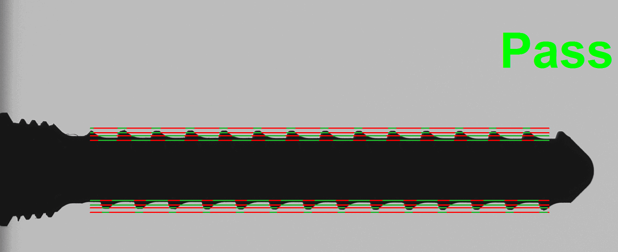
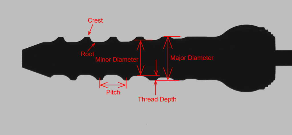
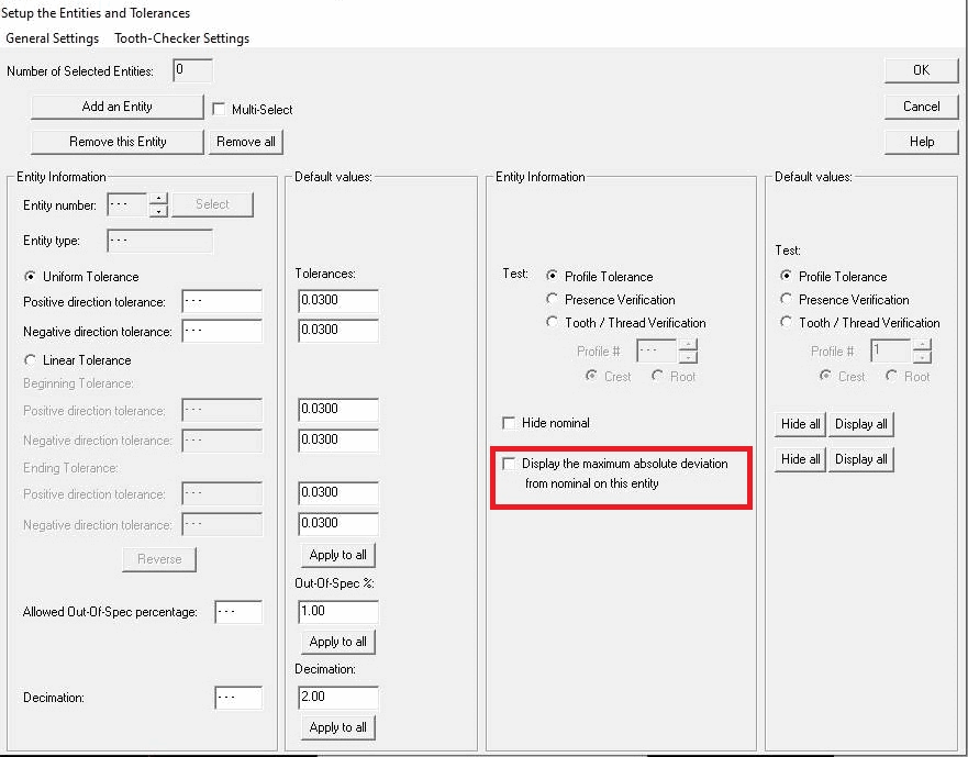
This update also includes a redesign of the CAD Auto-Pass/Fail “Entities” window. We’ve also added the ability to display the maximum (absolute) deviation from nominal on user-specified entities during CAD Auto-Pass/Fail® operations.

Maximum Deviation From Nominal on Entities


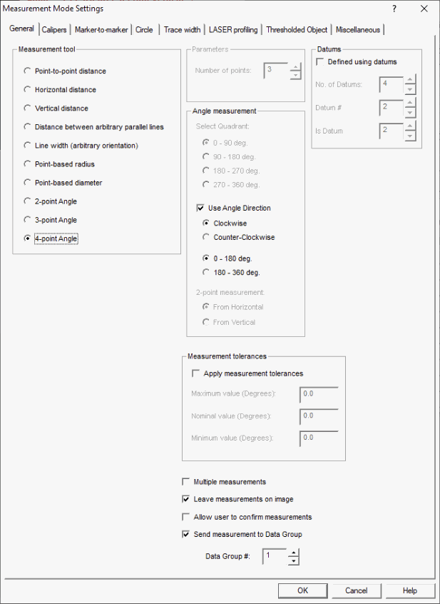
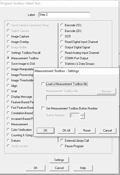
The Program Toolbox now includes a “Measurement Toolbox” option, allowing a program to automatically select an .mtb file to load and which button to select by default. This tool could be useful when a program needs to be paused to instruct operators to perform manual measurements before resuming the program again.

Program Toolbox - Measurement Toolbox


Also, the DXF Correspondence File now includes an additional optional parameter for which Measurement Toolbox file to load. This allows operators to automatically load VisionGauge® OnLine programs, auxiliary files, overlays, and/or a specific Measurement Toolbox by using the barcode reader. The DXF Correspondence File information has been updated with this data.


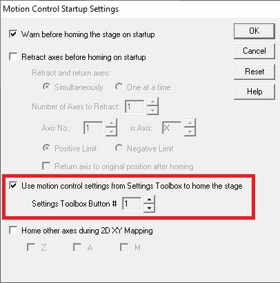
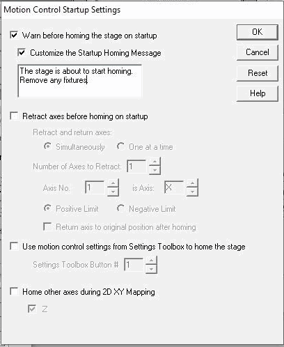
The Motion Control Startup Settings now contain an option to customize the startup warning message when the 2D XY Stage Mapping is about to begin its homing procedure. This notification window is much larger so it is more visible, and it allows multiple lines of customized text with Unicode support to give operators specific instructions for when the system starts.

Motion Control settings - customize startup message


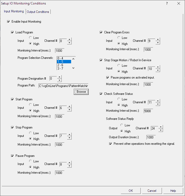
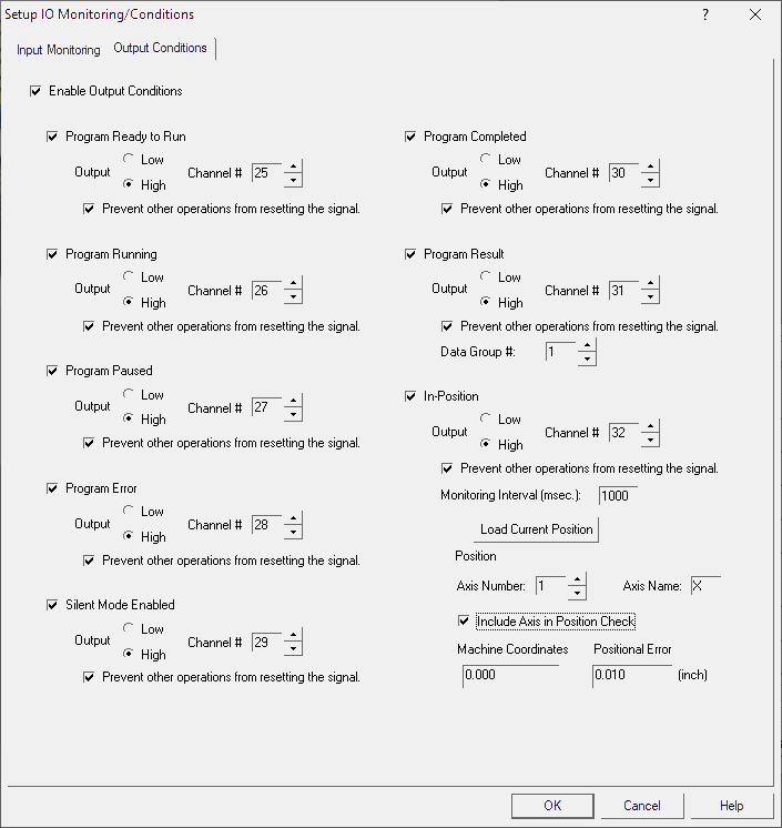
This set of updates also adds a Digital IO output condition for when a system’s Emergency Stop is triggered during program operation.


The Settings Toolbox now includes an option to save the current measurement units. This allows a Settings Toolbox button to reset the measurement units when it is recalled, which could be useful if different sets of measurements require different units.


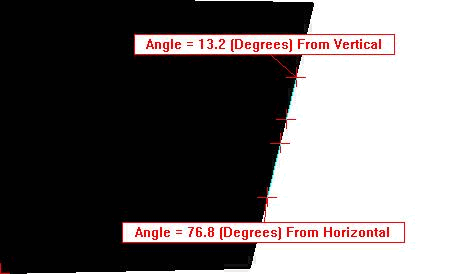
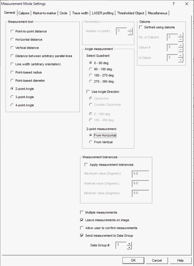
Finally, this update also includes a few performance enhancements, measurement improvements (Manual and Automated Perpendicularity measurements), small fixes that correct the display of camera names when multiple cameras are selected, and add additional support for Unicode in various input locations of the software.


Announcing the Super-Extended Travel Configuration 500 Series VisionGauge® Digital Optical Comparator


The new VisionGauge® Digital Optical Comparator 500 Series Super-Extended-Travel Configuration is designed to inspect large and heavy parts while still delivering performance, reliability, and high-accuracy measurements. These systems have up to 60” of travel and support loads of up to 300 lbs!

This innovative configuration is designed to provide optimal rigidity and eliminate any mechanical deflections. Everything is optimized to allow the system to produce very accurate measurements of long and heavy parts.


500 Series VisionGauge® Digital Optical Comparator - Super-Extended Travel Configuration

The Super-Extended Travel Configuration is powerful and widely-applicable. In particular, the Industrial Gas Turbine (IGT) / Power Generation industry greatly benefits from the use of this system for inspection of fir trees / root forms on buckets.

Super-Extended Travel 500 Series VisionGauge® Digital Optical Comparator inspecting fir tree / root forms on buckets
Fir Tree / Root Form Inspection with the Super-Extended Travel 500 Series VisionGauge® Digital Optical Comparator

Download the data sheet, visit the product page, and contact us for more information.


VisionGauge® OnLine version 14.09 is available for download


VisionGauge® OnLine version 14.09, dated April 14th, 2020, is available for download.


The following enhancements are available in the latest version:


A new 2-Point Angle Measurement tool has been added to VisionGauge® OnLine, allowing the user to define a line by 2 points and measure the angle of the line from horizontal or vertical.

2-point angle from horizontal and vertical
2-point angle measurement mode

Angle measurements in VisionGauge® OnLine are also now able to specify the direction of the angle over which to measure (Clockwise or Counter-Clockwise). This intuitive, new angle measurement option can be used as an alternative way to determine exactly which angle is measured in both 2-point and 4-point angle measurements – in manual measurement mode and automated programs. The tool returns the included angle in the direction indicated between the user-specified line 1 and line 2. The result can be between 0 – 180 degrees or 180 – 360 degrees, depending on the needs of the application.

Angular Direction measurement - Clockwise or Counter-Clockwise
Angular Direction measurement option


The Motion Control Settings now have an option to specify a particular Settings Toolbox button to load before starting homing operations when starting VisionGauge® OnLine. With this option, the homing procedure will use the motion control parameters saved in this button every time, instead of the last used settings on shutdown of the software.

Motion Control Settings - Settings Toolbox option

We have added a new DDE topic item, “PassFailReason,” to retrieve the Pass/Fail Reason string from a Data Group (if Pass/Fail reversal is enabled). We have also added the ability to request the most recently added value to a VisionGauge® OnLine Data Group for the following DDE items:

CharacterString
PassFail
MeasuredValue
UpperLimit
LowerLimit
Label
Nominal
PassFailReason
 

Previously, DDE requests could only specify the number of the item in the Data Group they wanted to retrieve. Now, by specifying ‘0’ as the target item number, the most recently added value in the Data Group will be returned.

For example, the DDE string VisionGaugeOnline|DataGroup!’2 MeasuredValue 0′ will now return the most recently added “Measured Value” from Data Group #2.


VisionGauge® OnLine version 13.99 and VisionGauge® version 10.91 are available for download.


VisionGauge® OnLine version 13.99, dated February 24th, 2020, is available for download.


The following enhancements have been made over the last few update versions:


VisionGauge® OnLine users may now specify the type of image that can be collected in a Data Group. Either the ‘raw’ image (without annotations or measurements) or the ‘displayed’ image (with measurements and ROIs) can be stored in a Data Group. It could be particularly useful to view the displayed image from a measurement if the Data Group shows a ‘Fail’ for a certain result to see inspect what went wrong.

Data Group options - Collecting results images


VisionGauge® OnLine’s IO Monitoring/Conditions feature allows users to a) configure specific output channels on which to output a signal when a certain condition is met during a operation of the software and to b) select an input channel to monitor for a signal to perform a specific action in the software.

When both Input Monitoring and Output Conditions are combined, VisionGauge® OnLine can be remotely automated by a robot or a controller that issues commands to the software. The Remote Program Communications feature was originally developed for communication by commands sent through TCP/IP or over a COM port, but this IO Monitoring/Conditions update allows either simplified automation using exclusively Digital IO’s or expands upon the existing Remote Program Communication feature-set with additional command/verification methods.

Input Monitoring allows digital input channels to be periodically scanned for a signal. When the target channel is activated, the software will perform specific actions. VisionGauge® OnLine presently supports the following Input signal monitoring actions:

  • Loading a program
  • Starting a program
  • Stopping a program
  • Pausing a program
  • Clearing Program Errors (when operating in ‘Silent Mode’)
  • Stop/Prevent Stage Motion
  • Check VisionGauge® OnLine Software Active Status (make sure the software is still alive and responding)
Input Monitoring - VisionGauge OnLine

Output Conditions allow the user to configure digital output channels to be activated when certain conditions are met during software operation. VisionGauge® OnLine presently supports outputting a signal when the following conditions are met or actions are performed:

  • Program is Loaded and Ready to Run
  • Program is Running
  • Program is Paused
  • Program Error
  • Silent Mode is Enabled
  • Program is Completed
  • Program Result (Pass/Fail)
  • In-Position (Stage is at a certain position)
Output Conditions - VisionGauge OnLine

It is possible to reserve output channels so programs and operators cannot accidentally output on those channels.

A new quick access button, accessible from the “Customize – User Interface” menu, also allows Input Monitoring and Output Conditions to be started or stopped by an operator.

Full documentation to describe how to use these input and output signals to work remotely (e.g. via a cell controller), is available.


VisionGauge® OnLine programs can take advantage of our True Position measurement tool. Our approach to True Position allows a user to define a Nominal feature whose position is compared to the Actual occurrence of that feature. Features are defined using datums that have been set in previous program steps. Nominal features can be defined using either Cartesian or Polar coordinates, which is convenient for different types of applications. Nominal features can also be offset using Basic Dimensions in the current measurement units.

VisionGauge® Online presently supports Cylindrical (point location) and Non-Circular (line) features of size, and the Nominal tolerance zone is displayed along with the Actual feature location. As with all VisionGauge® Online measurements, results, including a Pass/Fail result, can be output to Data Groups and other reporting options.

True Position measurement for Cylindrical Features of Size
True Position measurement for Non-Circluar Features of Size

Follow the link for more information about our True Position measurement software tool.


This update also adds support for Laser Angle Correction – to address the situation where a system’s lasers for measurements are not perfectly at 45 degrees with the stage.


Various fixes, performance enhancements, and improvements in memory management.


VisionGauge® version 10.91 is available for download.

This update includes support for a newer USB computer controlled illumination module, fully compatible with Windows 10.


Introducing VisionGauge®’s Patented “Tooth Checker™” tool

We’re happy to introduce VisionGauge®’s patented “Tooth Checker™” tool, specially adapted to check parts with teeth. This innovative new tool automatically locates, to very high accuracy, the crests and / or roots of the teeth and determines if they are within their tolerance band. It can also determine all other part characteristics, such as tooth pitch, thread depth, major & minor diameters, etc…

Bone screw teeth verification with the VisionGauge® “Tooth Checker™” tool

The Tooth Checker tool can verify that either crests, roots, or both, are in tolerance, using these crest & root points that the Tooth Checker tool has found, it can then automatically determine all other part characteristics:

VisionGauge Tooth Checker Nomenclature
Automatically check all part characteristics

This powerful new tool is perfect for quickly and accurately checking:

  • bone screws,
  • medical rasps,
  • gears,
  • fluted instruments,
  • threads & fittings,
  • and much more!


Click to view more information about the VisionGauge® Tooth Checker™, or download the application note.

Announcing the VisionGauge® Disk Inspection and Measurement System


The VisionGauge® Disk Inspection & Measurement System is the the ideal solution for automated, high-accuracy inspection & measurement of slots in turbine disks, both large & small. The system’s patented CAD Auto-Align™ & CAD Auto-Pass/Fail™ tools allow you to automatically check the slot profile, get deviations from nominal, etc…


VisionGauge Disk Inspection and Measurement System


Download the data sheet and contact us for more information.