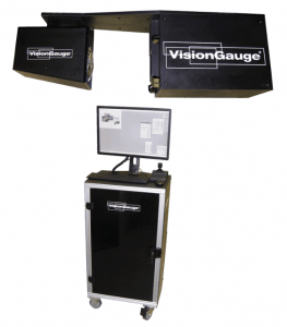
We’re pleased to announce the new 5X configuration of our 300 Series VisionGauge® Digital Optical
Comparator.
The 300 Series VisionGauge® Digital Optical Comparators are extremely cost effective Field-of-View
Systems that are ideal to inspect and measure smaller parts, very quickly. And the new 5X
configuration provides a wider field-of-view and a larger depth-of-field that extends the range of parts
that can be checked using the 300 series. Specifically, the new 5X 300 Series machine can
accommodate parts up to 6.4” (diagonal, i.e. 5.5” horizontal x 3.3” vertical) and up to 4” in height. The
new 5X 300 Series VisionGauge® also has a very long working distance that provides 15” of
clearance between the part and the lens.
Like all of the other 300 Series machines, it has very high-resolution optics that produce a very
geometrically accurate image and it also includes three independent light sources that are all LED based
and computer-controlled: transmitted (i.e. back) illumination as well as both on- and off-axis
reflected (i.e. front) illumination. This allows the system to produce crisp, sharp edges and perform
beautifully even when working with hard-to-image materials (for example: shiny, reflective or even
translucent surfaces) and difficult geometries (such as deep holes).
The VisionGauge® 300 Series machines produce a stunning super-high resolution image to carry out
fine, detailed inspections. And the system’s crisp & clear image is displayed on a single super-high resolution
monitor.
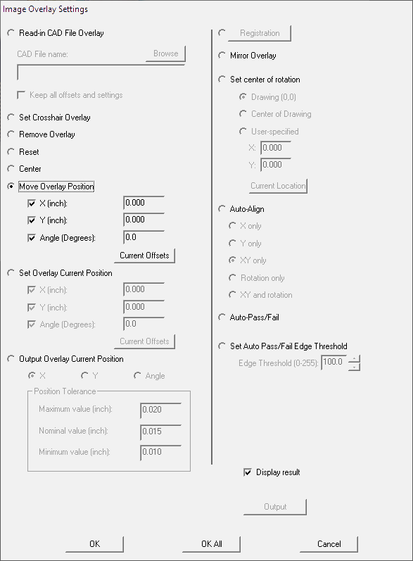
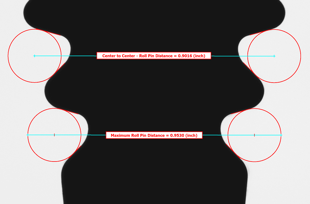
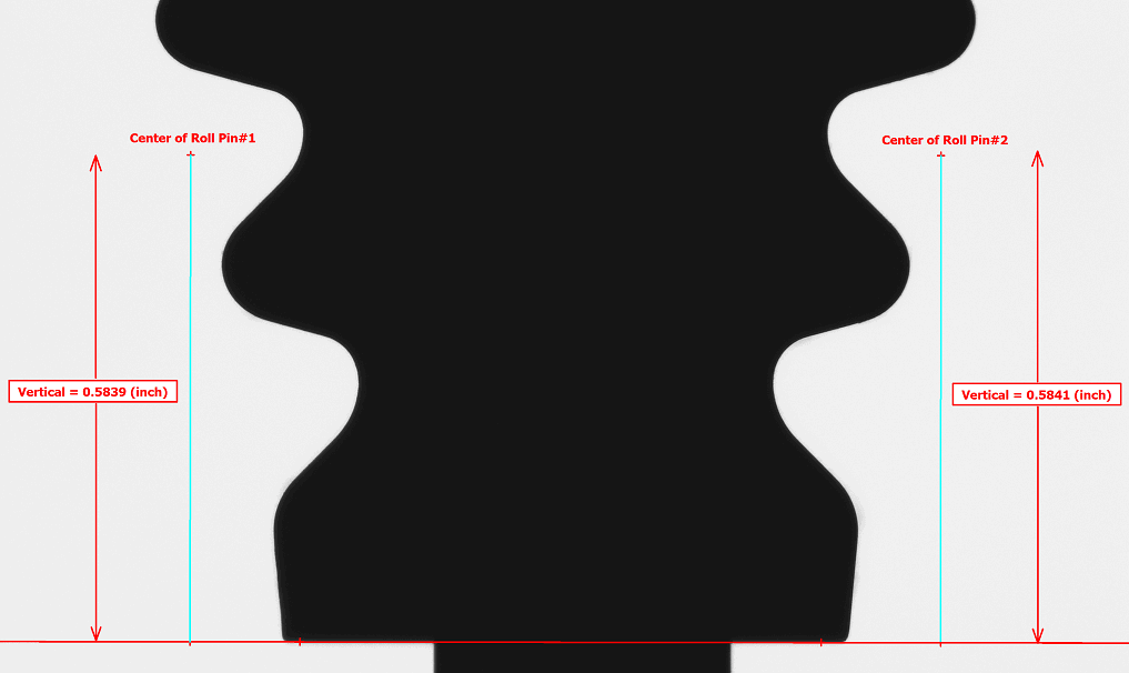
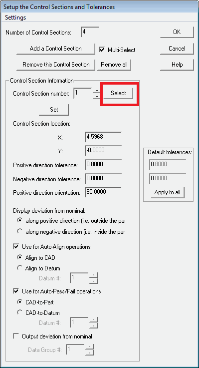
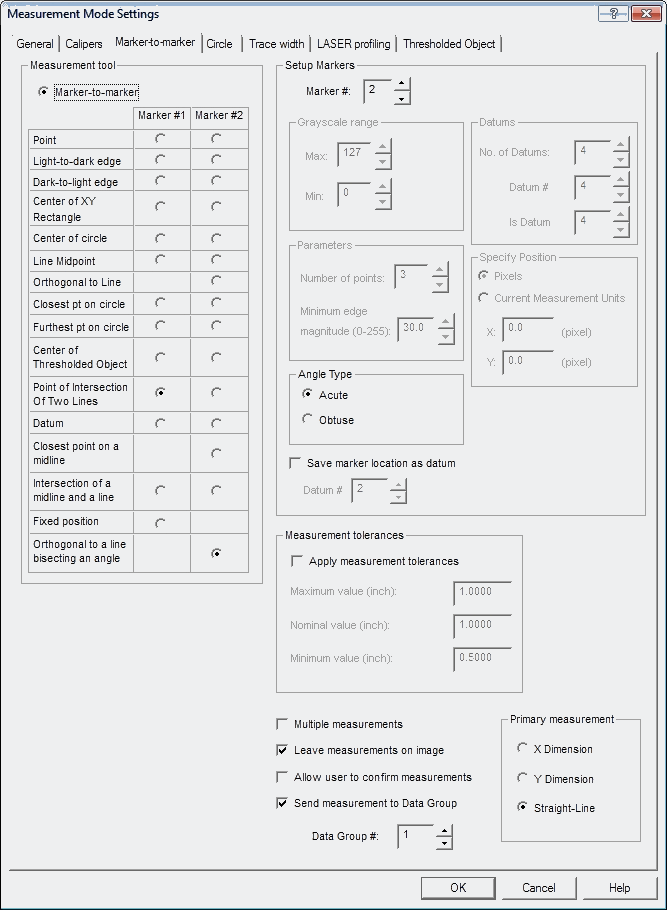
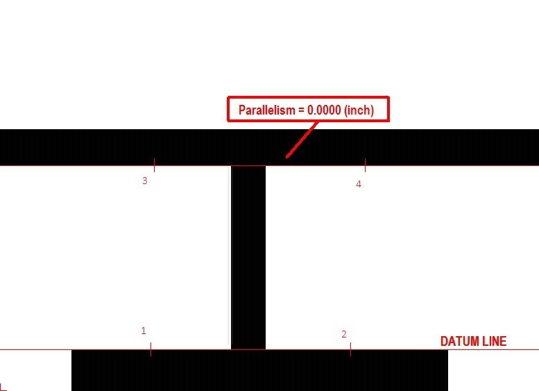
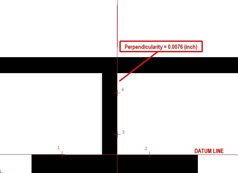
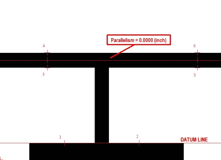
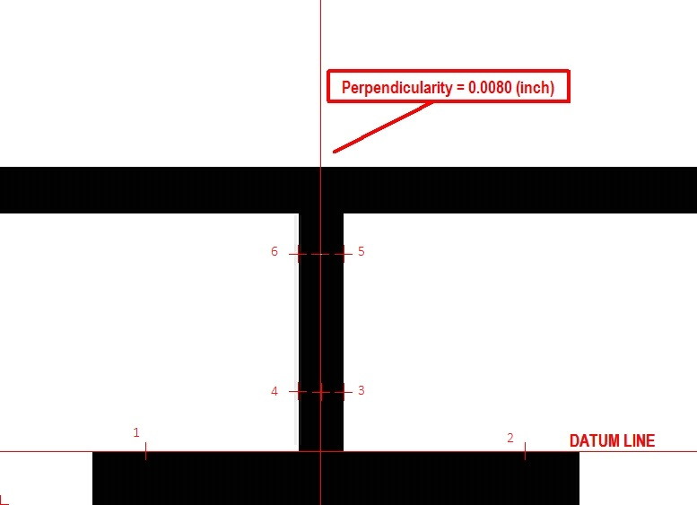
The 300 Series include all of the powerful VisionGauge® tools, including our patented CAD Auto-
Align™ and CAD Auto-Pass/Fail™ tools, for very fast automatic and operator-independent
comparison of parts to their CAD file, as well as VisionGauge’s® broad measurement toolset.
And because they are field-of-view machines and no motion is involved, the 300 Series
VisionGauge® systems are extremely fast. They can carry out hundreds of inspections and
measurements seconds after you’ve put the part down on the system. They can also accommodate
multiple parts at once.
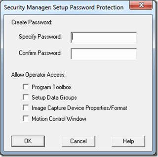
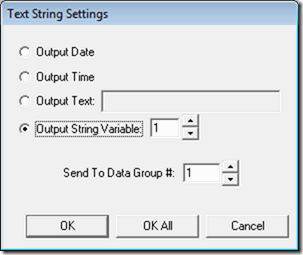
All 300 Series systems have an intuitive software interface and are extremely easy to use. They can
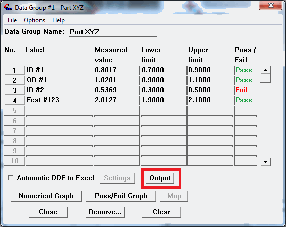
be setup to be operated using the system’s barcode reader and joystick. They have built-in SPC
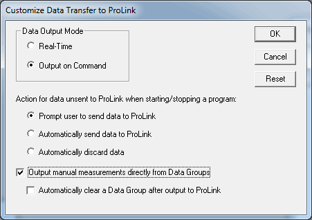
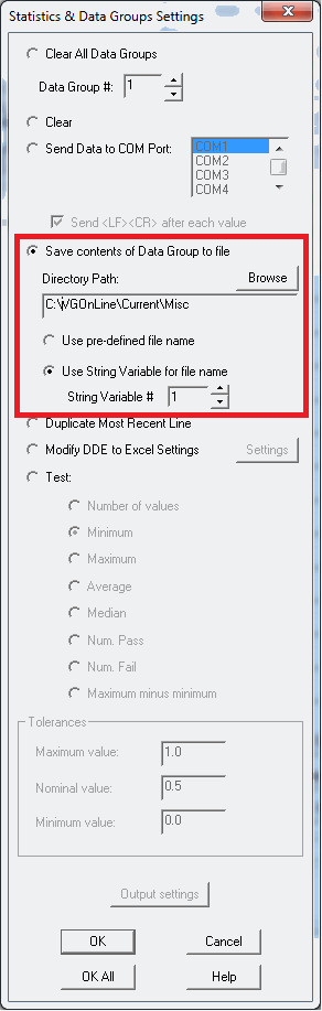
capability with charting & graphing and can automatically collect images and data. They also have
extensive data exchange capabilities.
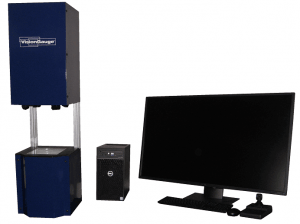
The 300 Series VisionGauge® systems have a convenient desktop configuration, no moving parts
and no consumable parts. They provide many years of reliable service with minimal maintenance.
They are perfect for both the shop environment and the quality control lab. They are complete, ready-to-
run Windows-based solutions that are delivered network-ready and include on-site installation,
NIST-traceable calibration & training.
This information is available for download in .pdf format: 5X 300 Series VisionGauge Digital Optical Comparator Machine Announcement