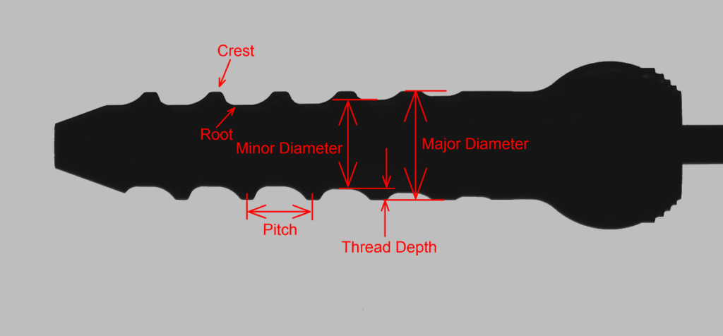
We’re happy to introduce VisionGauge®’s patented “Tooth Checker™” tool, specially adapted to check parts with teeth. This innovative new tool automatically locates, to very high accuracy, the crests and / or roots of the teeth and determines if they are within their tolerance band. It can also determine all other part characteristics, such as tooth pitch, thread depth, major & minor diameters, etc…
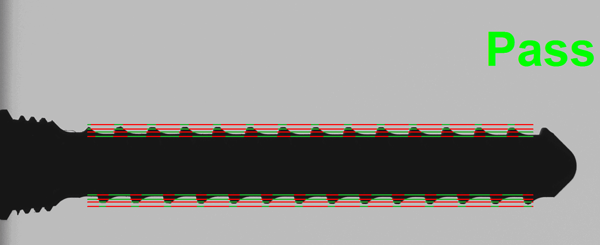
The Tooth Checker tool can verify that either crests, roots, or both, are in tolerance, using these crest & root points that the Tooth Checker tool has found, it can then automatically determine all other part characteristics:
This powerful new tool is perfect for quickly and accurately checking:
- bone screws,
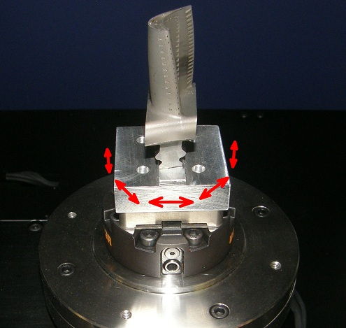
- medical rasps,
- gears,
- fluted instruments,
- threads & fittings,
- and much more!
Click to view more information about the VisionGauge® Tooth Checker™, or download the application note.