
Manufactured products always show slight deviations from their design. While this is expected, they can only deviate by a predetermined amount before they affect the product’s quality and function.
True position, or “position” in geometric dimensioning and tolerancing terms, is an invaluable concept in any manufacturing environment. It controls the degree of variation of specific features from their intended position — crucial for ensuring parts fit together and streamlining assembly. Understanding true position tolerancing is critical for a manufacturing operation requiring high degrees of precision and accuracy.
True position refers to how accurately a part’s feature is located relative to its intended design. It designates the maximum allowable deviation of that feature from the position outlined in the design specification. It specifies the diameter of the tolerance zone in which a feature must fall. In short, true position is the exact location defined by the product’s basic dimensions or other means.
In line with this definition, it’s crucial to understand that true position is a tolerance zone. It’s defined by a circle or a rectangle centered at its ideal location. The size of true position tolerance depends on the geometries specified within the blueprint. The feature is considered within acceptable tolerance levels if its location falls within the tolerance zone. As such, the true position error is the deviation between the actual location and the ideal position.
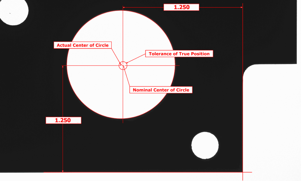
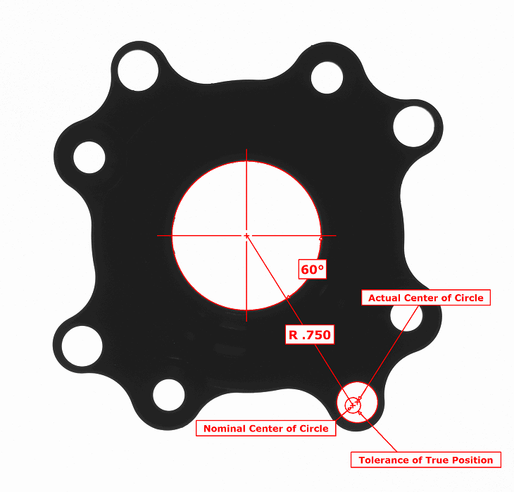
In geometric dimensioning and tolerancing, true position indicates the precise coordinate or dimension representing a feature’s nominal value, also called “basic dimension.” Position defines acceptable tolerance ranges of variation for the feature’s location. Both are critical for controlling the location of features such as holes, pins, and other geometries.
If the true position is a feature’s nominal position, a tolerance zone is the range of acceptable values within which that feature can vary from its nominal position. Depending on the part and feature, it can appear in two principal ways — rectangular and cylindrical. In simple terms, it’s a predefined distance in which features can be placed, and anything outside the tolerance zone is considered noncompliant.
VisionGauge® OnLine programs can take advantage of our new True Position measurement tool. Our approach to True Position allows a user to define a Nominal feature whose position is compared to the Actual occurrence of that feature. Features are defined using datums that have been set in previous program steps, using VisionGauge® OnLine’s rich measurement toolset to specify points. Nominal features can be defined using either Cartesian or Polar coordinates, which makes this software tool versatile in solving different types of applications. Nominal features can also be offset from a position using Basic Dimensions in the current measurement units.
The first step is to calculate a manufactured part’s position regarding its feature’s true position. Use the following formula:
True position = 2x (dx^2 + dy^2)^½
From there, you can use a functional gauge or coordinate measuring machine (CCM) to provide the required levels of accuracy and precision for measurement. You can also use VisionGauge® systems to take these measurements – even straight from the shop floor.
VisionGauge® Online presently supports Cylindrical (point location) and Non-Circular (line) features of size. The Nominal tolerance zone is displayed along with the Actual feature location. As with all VisionGauge® Online measurements, results – including a Pass/Fail result – can be automatically output to Data Groups and other reporting options.


As the VisionGauge® Digital Optical Comparator manufacturer, VISIONx is a trusted partner to organizations of all sizes and across various industries. We develop software, systems, and specialized hardware components to improve the accuracy and precision of your automated imaging, visual inspection, and high-accuracy measurement applications.
We conform to the ISO 10360 Standard for accuracy testing and performance certification of CMMs, and all of our system calibrations are traceable to the National Institute of Standards and Technology. Each of our systems comes with a full, detailed certificate of calibration, giving you peace of mind for your most accurate measurement requirements.

If you’re looking for the simplest and most accurate way to compare a part to a CAD file, look no further than VisionGauge® Digital Optical Comparators. Our products assist leaders across industries with increased optical inspection speed, agility, and reliability. Our visual measurement and image analysis software allows you to automate inspection, verification, and data collection.
Our VisionGauge® systems allow you to carry out inspections and measurements without operator-to-operator variation, boosting accuracy and productivity on the shop floor. Contact us with your application requirements to get started.
Learn More