VisionGauge® OnLine version 14.46, dated January 28th, 2021, is available for download.
New features and enhancements have been added:
Some of these new enhancements have to do with 5-axis applications. Now, there are 2 principal approaches that can be used to supply 5-axis coordinate data to VisionGauge® systems.
1) Data from the drill file
The most common approach consists in supplying the system data from a so-called “drill file”. This is the coordinate data for all of the holes that need to be inspected, as typically supplied to a LASER or EDM drill, for example. This data is generally output by a CAM software package. This data represents the (X,Y,Z,A,B) movements that the drill needs to carry out to bring each hole in position (under the wire, for example). This data is thus generally rotated about the drill’s trunnion and is expressed relative to the part’s (0,0,0,0,0).
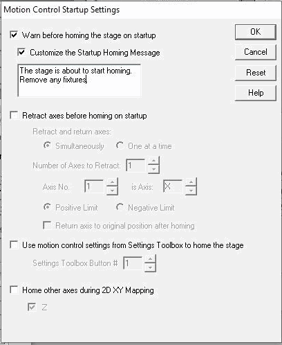
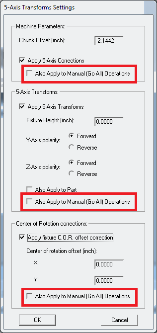
Using the “Chuck offset” and “Fixture height” information from the “5-axis Transform Settings” window (accessed through the “Motion control” window, as shown below), VisionGauge® OnLine can use this “drill file” information directly (using VisionGauge®’s built-in 5-axis transform) to effectively rotate the data about its own trunnion and still expressing all coordinates relative to the part’s (0,0,0,0,0)), i.e.:
2) “Raw” un-rotated data:
Starting with the latest software update, a second approach is possible for supplying 5-axis hole data to the system. With this approach, when we check the “Apply to the part” checkbox in the above “5-axis Transform Settings” window, then we can simply supply the (X,Y,Z,A,B) coordinates of the (un-rotated) holes, as always expressing all coordinates relative to the part’s (0,0,0,0,0). In this case, VisionGauge® OnLine carries out all of the required rotation calculations. This approach is very convenient if you don’t have a drill file, or if you don’t even have any CAM software.
Note that both approaches are absolutely equivalent. Generally, users will choose one or the other based on data availability and convenience…
Also, please note that we’ve also refreshed our 700 Series brochure with some new and updated information.
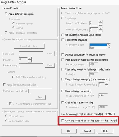
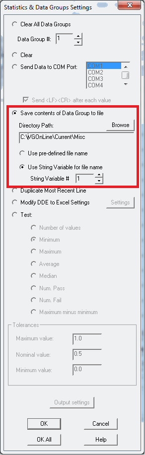
We have added an option to allow Live Video to run in VisionGauge® OnLine while working outside of the software. By enabling this option in the “Settings – Image Capture Settings”, VisionGauge® OnLine will no longer stop live video when clicking in another window or typing outside of VisionGauge® OnLine. This may mostly benefit users of the “Standard” edition of VisionGauge® OnLine if they require live video to stay on when working on programs outside of the software.