Application note,
Applications,
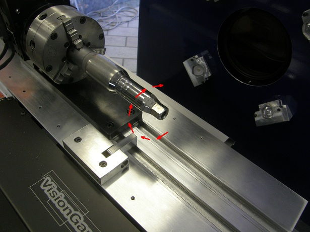
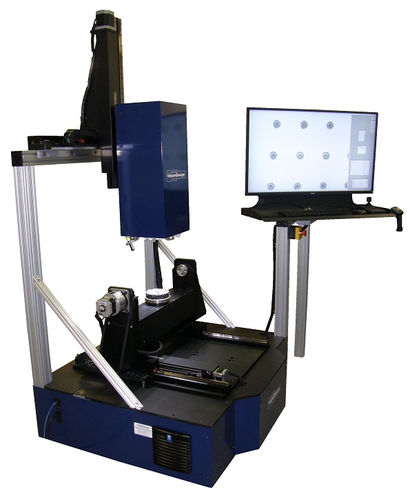
Digital Optical Comparators,
News/New Developments,
Software Feature,
VisionGauge® Online
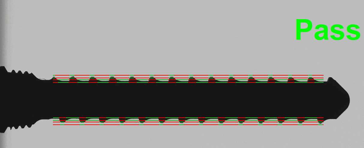
Introducing VisionGauge®’s Patented “Tooth Checker™” tool
VisionGauge's Patented Tooth Checker Tool Is The Perfect Device For All Part Inspection & Measurement Needs. Contact Our Team Today …January 8, 2020
1 MIN READ