The optical comparator (profile projector) has been used in quality control in the manufacturing industry since it was first patented in 1925. The overall design has changed little in that time, with the exception of some digital and software enhancements. The continuing popularity of this device is a statement of how useful it is for optically checking parts for conformance and deformities.
Here we will discuss what optical comparators are, as well as the following questions: what is an optical comparator used for, how does it work, and how do traditional models compare to digital ones?
Table of Contents
- What is an Optical Comparator?
- How Does an Optical Comparator Work?
- How to Use a Traditional Optical Comparator
- Limitations of Traditional Optical Comparators
- Digital Optical Comparators vs. Traditional Optical Comparators
- Using Traditional Optical Comparators vs. Using Digital Optical Comparators
- How to Use a Digital Optical Comparator
- Applications of Digital Optical Comparators
- VisionGauge® Digital Optical Comparators
Optical Comparator Definition
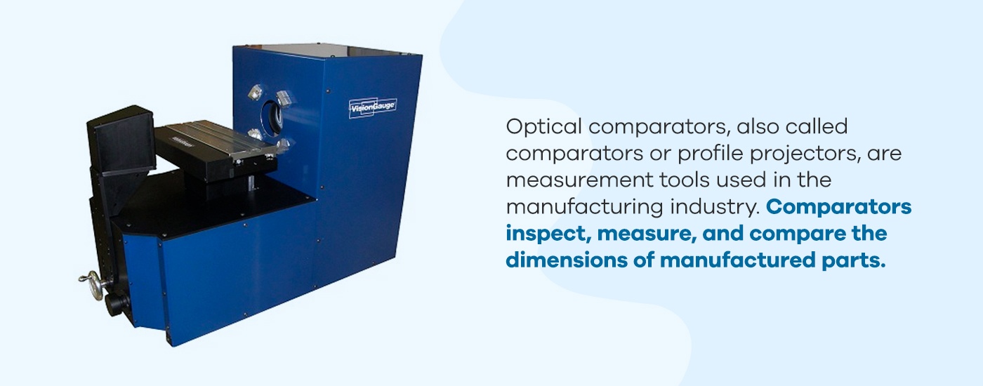
Optical comparators, also called comparators or profile projectors, are measurement tools used in the manufacturing industry. Comparators inspect, measure, and compare the dimensions of manufactured parts. These measurement tools function using the principles of optics by utilizing illumination, lenses, and mirrors to project a magnified silhouette of a part upon a screen. Doing this compares the part to its prescribed limits.
Optical comparators are used to check for both dimensional accuracy and surface defects, such as scratches and indentations. In short, they allow for non-contact measurement and observation, minimizing handling while still allowing for close inspection.
There are two primary configurations of optical comparators: horizontal and vertical. Here’s how they work:
- Horizontal comparators: In a horizontal model, the optical comparator’s light travels horizontally so the viewer is looking at a silhouette taken from the side of a part. This model works best for parts held in a fixed location — some examples include screws that are fixed in place or castings that must be held in a vise.
- Vertical comparators: In a vertical model, the optical comparator’s light travels vertically so the viewer is looking down on the part. This works best for flat components that can lie on the work stage, such as gaskets. They also work well on flexible or soft elements that need to lie on a flat surface to provide an accurate measurement.
Optical comparators of both types can be found in manufacturing shops and lab environments related to quality control. They are most popular in industrial sectors, including the scientific, automotive, medical manufacturing, aerospace, and defense industries.
How Does an Optical Comparator Work?
Optical comparators have changed little since they were invented in the 1920s — the reason for this is that the technology uses optics, which have only changed in quality, not function. Optical profile projectors work similarly to overhead projectors commonly used in classrooms. A light is directed through a stage to a series of lenses and mirrors, which then project the silhouette of whatever is on the stage onto a screen.
Optical comparators use this same principle. A part is affixed to a stage and a light source shines on it, resulting in a shadow image of the part. The shadow is magnified with lenses and bounced by mirrors onto the back of a screen. This screen is fixed at a known distance for measurement purposes.
Optical comparators can vary in the size and magnification of the projected image. Both of these metrics depend on the optics and screen size of the comparator. Screen sizes for optical comparators range from 12 to 36 inches, though models with larger screens are available. However, larger screen sizes are only possible with larger enclosures, as a greater distance is required to generate a bigger image without distortion.
Another way that optical comparators differ is in the measuring processes they use. There are three different measuring processes for comparators:
- Silhouette measurement: The simplest measurement method is to project a silhouette of the image onto a screen for measuring. Because the magnification is known, the silhouette can be used to gain accurate measurements.
- Point comparison: The second measurement method is to compare the image’s silhouette to prescribed plan points on a screen. The part’s silhouette is centered on the screen and the user moves the stage to hit various points on the screen. This measures how much the stage had to move to match the part to the point.
- Software analysis: The last measuring process is digital, using software to analyze and measure the image generated by the optical comparator.
The first two methods are used by traditional optical comparators and are the most common in the industry. The third is employed by digital optical comparators, which handle the entire process electronically.
How to Use a Traditional Optical Comparator
Using an optical comparator with a traditional setup, the steps are similarly simple:
- Placement: First, the operator must turn on the optical comparator and place the part to be observed on the staging area.
- Alignment: When the part’s image is projected on the comparator’s screen, the operator must place an overlay on the screen. The optical comparator overlay, also known as a template or Mylar, is a part drawing printed on a transparent overlay that is scaled to match the magnification of the comparator. The operator must align this overlay with the part’s image.
- Comparison: Once the overlay is placed, the operator compares the drawing to the image and identifies any discrepancies. From these discrepancies, the operator will determine if the part is within tolerance.
This is the process used for most traditional optical comparators, though there are various methods available for this technology. For example, instead of an overlay with a part plan, an overlay may feature a grid or concentric circles to allow for more precise measurements of a part. Alternatively, a point comparison method may be used, where the image’s silhouette is centered on the screen compared to an overlay. The user then moves the stage to hit prescribed points on the overlay, measuring how much the stage had to move to match the part to each point.
Limitations of Traditional Optical Comparators
Profile projectors are generally straightforward and require little training to use. Traditional optical comparators that use silhouette measurement or point comparison simply require the user to fix a part in place and observe the on-screen image.
While traditional optical comparators are easy to use and operate, they also present disadvantages because of their simplicity. Some primary flaws of traditional optical comparators include the following:
- Limited complexity required: Production parts are becoming more complex, and observing them at more than one angle is becoming increasingly necessary. However, traditional comparators don’t accommodate this well.
- Less accurate: How accurate is an optical comparator? Although traditional optical comparators can obtain very accurate measurements, today’s modern parts require tighter tolerances, reducing the room for error that is allowed with any manual measurement method.
- Labor intensive: Traditional optical comparators can only measure one part at a time. This poses a problem when needing to inspect large quantities of parts, as is often needed in the manufacturing industry. This is particularly the case when inspecting large quantities of parts at once, since a vision system can allow you to place multiple parts for inspection on the stage at the same time.
- 2D limitations: Traditional optical comparators can only project 2D images onto a screen, which can present issues for analyzing multiple dimensions at once.
Although these limitations present no issues for non-repetitive tasks used to analyze 2D parts, anything outside of this defined operating bubble is an obstacle for traditional optical comparators. For large-scale, complex analysis, a different model is necessary.
Digital Optical Comparators vs. Traditional Optical Comparators
Where traditional optical profile projectors fall short, digital models pick up the slack. Manual comparator technology is highly useful in small-quantity applications, but with the rise of more complex parts and large-scale manufacturing, automation is necessary. Digital optical comparators present the solution.
Digital optical comparators offer the following advantages:
- Automation capabilities: These models use software and cameras instead of human eyes to analyze and measure parts. The software automates the measuring process and completes it more quickly than a human can.
- 3D capabilities: Digital optical comparators can use multiple lighting techniques and 3D inspection methods to analyze parts in all three dimensions.
- Quantity management: The automated nature of digital optical comparators means they can analyze multiple parts automatically without human intervention.
- Accuracy: By removing the potential for human error, digital optical comparators are extremely accurate in their measurements, which is necessary for many modern industries and technologies.
These advantages effectively maximize the accuracy of optical comparator measurements while reducing labor.
Using Traditional Optical Comparators vs. Using Digital Optical Comparators
While traditional optical comparators are generally straightforward to use, they present significant disadvantages to both users and clients. Some of the most significant drawbacks include:
- Little quantifiable data: Measurements using traditional comparator methods can be subjective and difficult to quantify. When comparing a part to an overlay with a plan, the goal is simply to pass or fail the part. However, clients are increasingly asking for quantifiable data about each deviation, which is difficult to achieve with this method.
- Limited flexibility: Traditional optical comparators only project 2D images onto a screen. This presents an issue in an industry where parts are becoming increasingly complex and require analysis from multiple angles. With a traditional optical comparator, an operator analyzing a complex part must physically move the part and utilize multiple overlays for analysis, which can be difficult depending on the part’s geometry and requires a significant input of time and labor.
- Reduced accuracy: Today’s parts require tighter tolerances and more quantifiable data. Although traditional optical comparators are capable of gathering accurate measurements, this requires a highly trained operator. Additionally, the manual nature of a traditional optical comparator always leaves room for human error.
- High costs: Traditional optical comparators incur significant costs over time. Overlays are expensive to produce, and the labor input required for traditional optical comparators is significant, especially for complex parts.
In short, traditional optical comparators require extensive training to use properly and need significant labor input. While these limitations may be a non-issue for small operations that work with simple parts, the manufacturing industry as a whole is quickly growing in scale and complexity. It needs optical comparator tools that can keep up.
Manufacturing companies need tools that are quick and easy to use to handle large quantities of complex parts. This is where digital optical comparators come into play. Digital optical comparators take the concept of traditional optical comparators and apply new technology to key areas. The result is an automated technology that is faster and easier to use, reducing the labor input of operators.
How to Use a Digital Optical Comparator
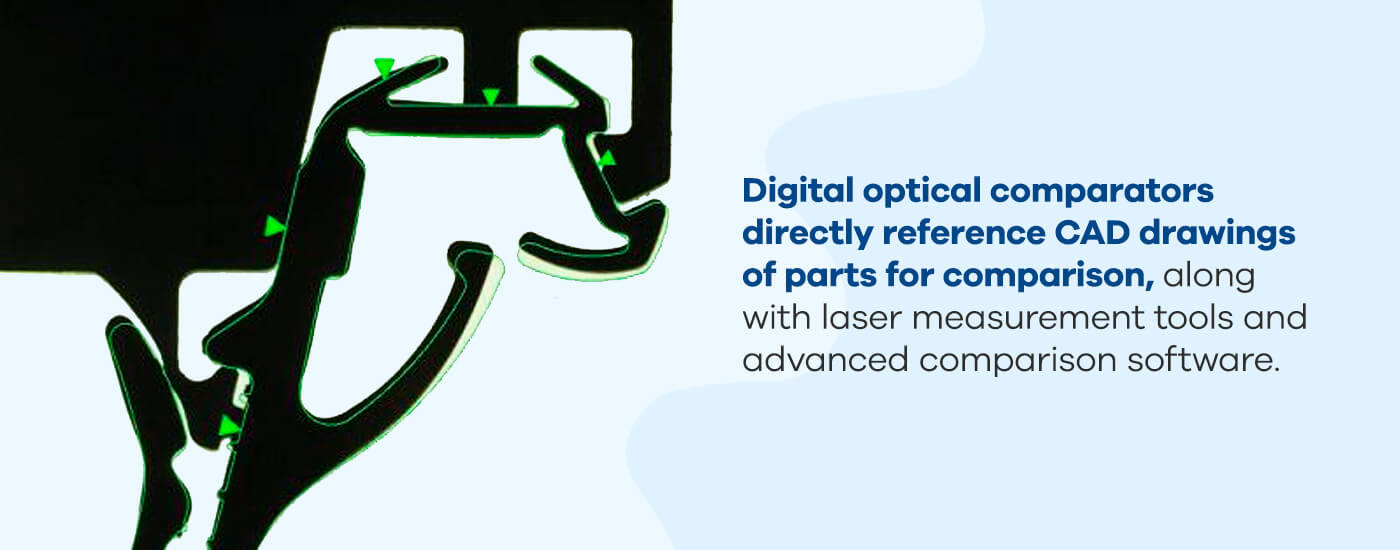
Digital optical comparators pick up the slack where traditional models fall short. Digital optical comparators, like traditional models, utilize optics for comparing a part to its plans. However, digital optical comparators do so by augmenting the existing comparator technology with a combination of measurement and analysis tools. Digital optical comparators directly reference CAD drawings of parts for comparison, along with laser measurement tools and advanced comparison software.
So what does this mean for operators? Essentially, digital optical comparator instructions for operators are pared down from three steps to one: place the part on the staging area. From there, the digital optical comparator does the rest. The system will automatically handle alignment and comparison, providing a pass/fail result along with analytical data supporting the decision.
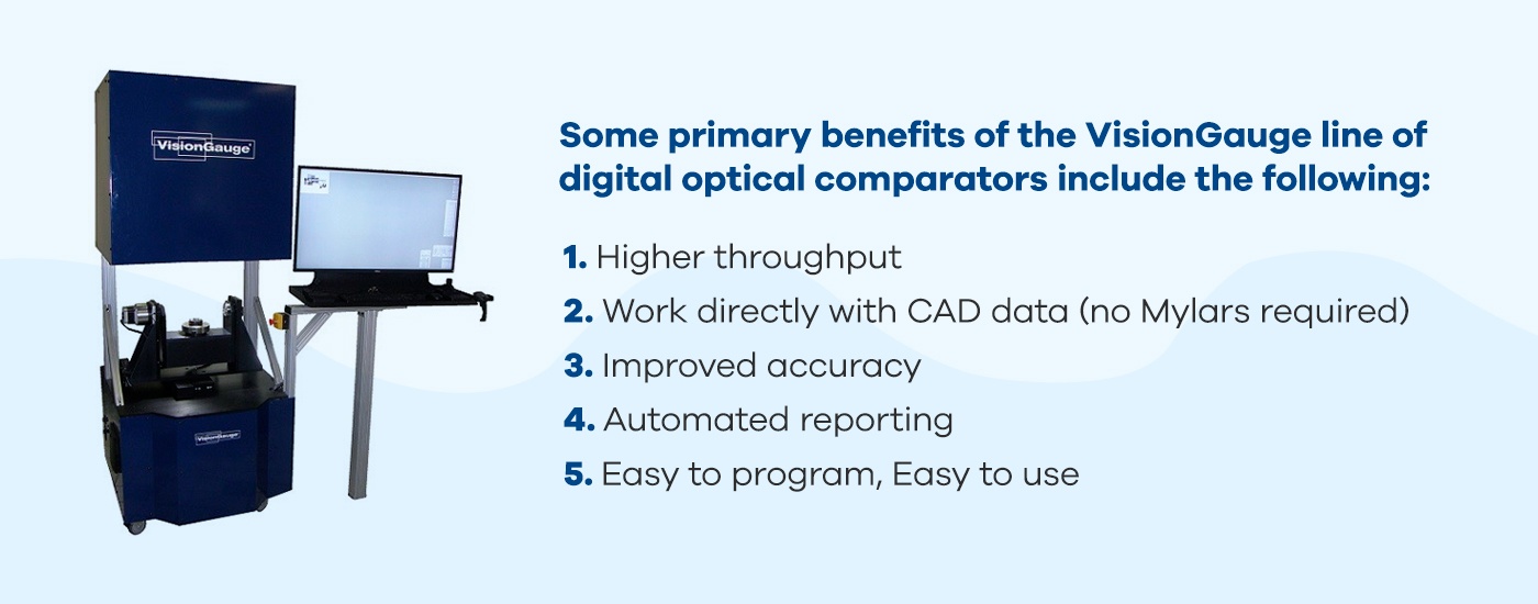
In addition to the simplified use, digital optical comparators also offer the following advantages:
- Fast automation: Digital comparators use software and cameras to analyze and measure parts automatically. The system automatically aligns and compares parts with their CAD drawings, doing so within seconds. This minimizes operator input and allows for higher throughput.
- 3D capability: Digital optical comparators use multiple lighting techniques, additional positioning stages (e.g. rotary stages), and lasers to analyze parts in all dimensions, allowing for quick, one-shot measurements with minimal operator interference.
- Improved accuracy: Digital optical comparators are extremely accurate, accomplishing highly detailed measurements automatically and eliminating the potential for human error. Additionally, the digital comparator software provides detailed documentation backed with thorough data, including measurements, statistics, and pass/fail results for parts and batches.
While automation is one of the many significant benefits to using the VisionGauge® Digital Optical Comparator, the system is also accurate and efficient when used manually by an operator wanting to perform direct measurements on a part or make manual comparisons of a part to its CAD file. The VisionGauge® software interface is intuitive and easy-to-use even for manual operation: Operators can quickly load part CAD files and pre-programmed inspection routines with the system’s barcode reader, and the stages and overlay can be manually controlled with the system’s industrial-grade joysticks. Both automated and manual operation modes produce highly accurate results and complete documentation.
Applications of Digital Optical Comparators
Companies across a range of industries use digital optical comparators to solve various applications. Below are some common digital optical comparator uses and applications:
- Aerospace: Aerospace manufacturers use optical comparators to inspect and measure turbine disks and slots, cooling holes, turbine blade fir trees, seal slots, and slots on five-axis parts. Digital optical comparators improve accuracy and repeatability, increase throughput, and collect electronic documentation – all essential functions in the aerospace industry.
- Automotive: In the automotive industry, digital optical comparators inspect flexible auto seals and trim, measure, and inspect various components and parts. Digital optical comparators are ideal for comparing seals against CAD data, especially when the components are difficult to inspect.
- Bearings: Accuracy in manufacturing is critical for precision bearings. A digital optical comparator checks bearings on the shop floor and works much faster and more efficiently than traditional methods.
- Machining: Digital optical comparators include tools designed to check machining parts. The patent pending VisionGauge® Tooth Checker inspects screw teeth.
- Medical devices: Multiple tools are available for inspecting and measuring medical devices and implants with digital optical comparators. For example, the VisionGauge® Tooth Checker tool can examine implant screws. Optical comparators can also inspect stents, medical rasps, orthopedic implants, and more.
- Defense/military: Equipment used for military and defense purposes also benefits from inspection by a digital optical comparator. VisionGauge® can efficiently automate inspecting parts with large numbers of holes or other features and works much faster than other systems.
- Power and energy: Micro-hole inspection also has applications in the power and energy industry. Additionally, cooling hole inspection and measurement tools measure the location of laser-drilled and electrical discharge matching (EDM) holes.
- Tool and dye: Digital optical comparators are ideal for use when you need to inspect thread rolling dies. You can set the system to automatically identify and check features based on your specifications.
Digital optical comparators have many applications in addition to those listed above.
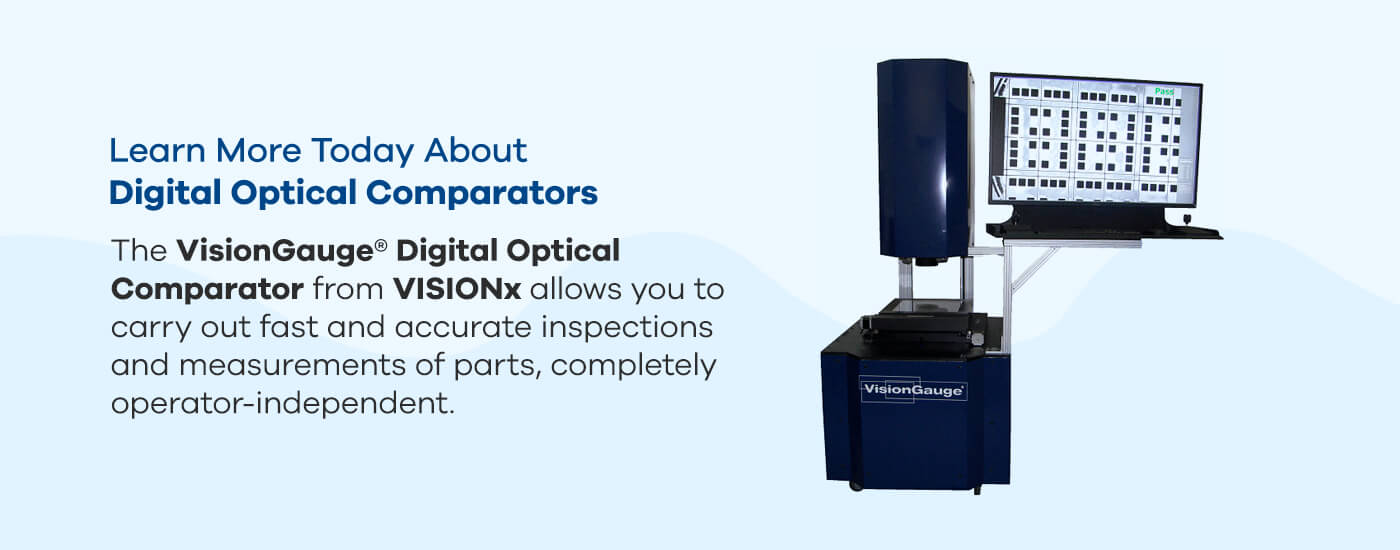 Learn More Today About Digital Optical Comparators
Using an optical comparator doesn’t need to require extensive training or massive labor inputs. Simplify your optical inspection with VISIONx, Inc’s VisionGauge® Digital Optical Comparator. Our digital optical comparator is an advanced optical analysis tool that maximizes the function of optical comparator technology. They are extremely precise yet easy to use, delivering fast, high-quality results. They allow you to carry out fast and accurate inspections and measurements of parts, completely operator-independent.
VISIONx, Inc. has multiple optical comparators for sale. Each model presents competitive advantages and includes VisionGauge® software with a wide range of applicability. On top of our optical comparators, VISIONx, Inc. develops, sells, and supports software, systems, and hardware for other automated imaging, visual inspection, and measurement solutions. With powerful and easy-to-use products, you can rely on VISIONx, Inc. for custom or standard solutions in various industries — from aerospace and automotive to electronic and medical device manufacturing.
To learn more about VISIONx, Inc.’s products, browse through our list of offerings or contact us online today.