Hole Array Inspection and Measurement

VisionGauge® Digital Optical Comparators for Fast, Easy, and Accurate Hole Array Inspection & Measurement

Some applications involve parts with a great many holes (for example: many thousands) that need to be checked. These parts can be made of different materials. We’ve worked on metal, carbon, ceramic and silicon parts like this. These parts are sometimes referred to as hole arrays or micro hole arrays.

These types of parts are used in different industries. Defense, semiconductor manufacturing, aviation and aerospace are a few industries that come to mind. Depending on the application, the holes can have different functions. Often, their presence has something to do with controlling a flow (of a gas, of particles, etc.). There could be different reasons for such flow control:  It might be for cooling purposes, for uniformity of dispersion, etc. Gas Distribution Plates, used in semiconductor manufacturing and plasma reactors, are a typical example of these types of parts.

These parts are typically difficult to manufacture, and the holes have obviously been included in the part’s design for a reason, i.e. they have a role to play, typically a key one. So, most often, these parts need to be inspected in great detail to ensure that they will meet their requirements.

microhole array inspection

There are many different parts, across many different industries, that have a great many holes that need to be inspected

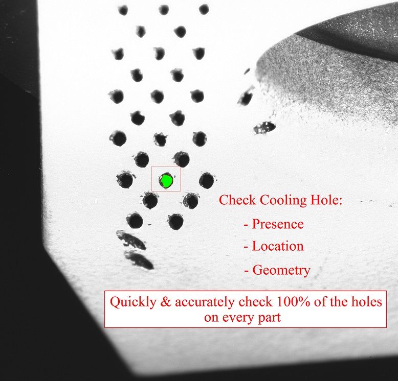
Typically, the inspection needs to ensure that all of the holes are present and that their location and geometry are correct. Note that, in some cases and depending on functional requirements, the holes might not necessarily be round. In fact, we’ve come across quite a wide range of different hole geometries in these types of projects.VisionGauge automated hole inspection programs have no limits to hole geometry or placement

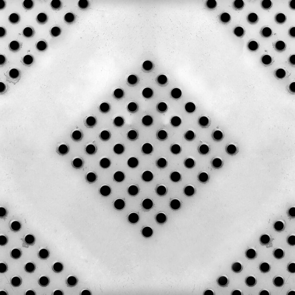
Inspecting 100% of the holes can be both challenging and extremely time consuming. Most inspection systems, to obtain the needed level of detail, proceed hole-by-hole. If a part has 18,000 holes, for example, then even if every individual hole can be dealt with quickly, this approach still takes a tremendous amount of time to cover the entire part. We’ve heard of parts for which a complete inspection required full days and even multiple days.

The VisionGauge® Digital Optical Comparator is especially well suited to applications where parts have a very large number (e.g. many thousands) of closely grouped holes as it can analyze all of the holes visible in the entire field-of-view at once, very quickly and accurately. This approach involves absolutely no compromise on accuracy. All the while, throughput is increased tremendously.

Motion operations (i.e. physically moving the part or the camera) are typically the most time-consuming steps in inspection and measurement programs. In applications involving a large number of closely grouped holes, the optimized approach offered by VisionGauge® drastically reduces the number of motion operations needed since it doesn’t involve hole-by-hole movement but rather simply ensuring that the entire part has been scanned through field-of-view-by-field-of-view coverage.

Furthermore, VisionGauge® can analyze every individual hole in the field-of-view extremely quickly (e.g. milliseconds) as it captures a great many measurement points (typically: thousands) almost instantly.

Multiple hole location inspection (starting image)
Multiple hole location inspection (selection image)

Analyzing all of the holes in VisionGauge®’s large field-of-view in a single operation provides for an enormous speedup

Outline of the Inspection Approach:

In broad terms, this approach involves the following steps:

  1. Scanning the part, field-of-view by field-of-view
  2. At every field-of-view:
    • Capturing an image
    • Locating the holes
    • Saving the hole data (i.e. X,Y location, & geometry)
  1. After the entire part has been scanned, comparing the measured hole data against the nominal hole data

So, in terms of programming, the program involves only a small number of instructions.

Scanning the Part

This is done using the software’s “Motion Control” tool, i.e:

Motion control step setup for microhole array inspection

As can be see above: we select the “Scan” mode, specify the 2 corners of the rectangular area to be scanned and also specify an overlap to ensure that every hole is completely visible in at least one field-of-view (i.e. we want to avoid that half the hole is visible in one field-of-view and that the other half is visible in the next field-of-view).

Capturing an Image

This is done using the software’s “Image Capture” tool.

Locating the holes and saving the hole data

This is done using the software’s “Counting & Sizing” tool, i.e.:

Hole array counting & sizing configuration

This is an extremely general-purpose tool and you shouldn’t be taken aback when you see all of the parameters in the above window as – for this application –  we don’t need most of them.

Here we simply set thresholds to separate the holes from the background (we can use adaptive thresholds that are extremely powerful…). We also tell the tool to disregard the holes touching the borders:  With the scanning overlap, this is how we ensure that every hole is seen completely at least once.

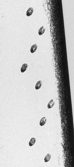
The images below, taken from a previous application of this type, illustrate this tool’s operation. Note that for reasons specific to this historical application, the images below are front illuminated (i.e. captured using reflected illumination). The holes thus appear dark and the part light. In most applications, we would use back (i.e. transmitted) illumination, which yields even more robust results.

Front-illuminated hole-array inspection

Raw image

Hole array image analysis

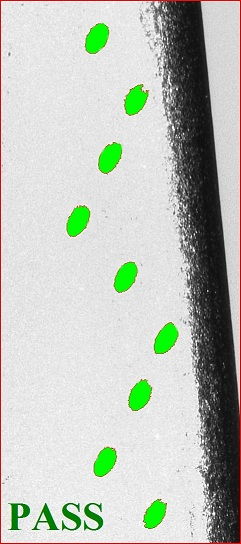
Analyzed image (i.e. the holes extracted are in red)

Comparing the measured hole data against the nominal hole data

This is done using an external “Hole Checker” library that we have developed for exactly these types of applications. It reads-in a user-supplied text file with the nominal hole data (i.e. X,Y location and diameter, in the most basic case). It then compares the measured hole data to the nominal hole data. Note that if (because of the Image overlap) a hole was measured more than once, it is only the first of these measurements that is considered.

This “Hole Checker” tool produces a text file with 1 line per (nominal) hole, every line containing:

  • The hole number (same as the input / nominal file)
  • The hole nominal position (same as the input / nominal file)
  • A PASS or FAIL indicating if the hole was found
  • If the hole was found: the measured X & Y hole position
  • If the hole was found: the measured hole diameter

Note that VisionGauge®’s “Map View” tool can also be used to provide a graphical layout of the results, as well as allow easy “operator review” of the results (i.e. click on a hole and the software brings it back in the middle of the field of view, so that the operator can revisit / review, etc.).

VisionGauge®’s extensive CAD-Comparison capabilities

Of course, VisionGauge® also has extensive CAD-Comparison capabilities (i.e. patented CAD Auto-Align™ & CAD Auto-PASS/FAIL™ tools). These can also be useful in this application, at the very least for “quick inspection & verification” purposes. For example: bring up the CAD file and quickly manually “move around the part” and generally asses the alignment of the holes to the CAD data. This can provide a quick confirmation / sanity-check as to whether or not “things look good” and glaring defects will “jump out” at the operator.

Summary

VisionGauge® offers powerful and unique tools that allow for highly optimized inspection and measurement of parts with a large number of holes, much faster than with traditional approaches. The results produced by VisionGauge® remain very accurate, to the instrument’s full resolution. Furthermore, these fast, accurate, and fully-automated inspections are very easy to setup with VisionGauge®.

Download a .pdf version of this VisionGauge® Digital Optical Comparator Application Note.

Read more about other applications VisionGauge® software and systems are being used to solve.

Cooling Holes Inspection / Cooling Hole Measurement and Verification

 The 700-Series VisionGauge® Digital Optical Comparator is the Perfect Solution for EDM- and LASER-Drilled Holes and Slots Inspection and Measurement

The 700 Series VisionGauge® Digital Optical Comparator is widely used by manufacturers across a broad range of industries (including aerospace and power generation) to inspect and measure EDM- and LASER-drilled cooling holes and slots:

  • Automatically verify hole presence & accurately measure hole locationCooling Hole Inspection - Verifying Presence, Shape, and Location
  • Supports both round and shaped holes
  • 5 axes of motion (X, Y, Z, Rotary, Tilt) to properly view parts from all sides & angles
  • Quickly, easily, and accurately inspect 100% of the holes on your parts
  • Robust shop floor design
  • Can output the hole offsets which can be used to modify EDM drilling programs
  • Mounting system allows your parts to go directly from the EDM drilling machine to the inspection and measurement system without re-fixturing (quick & easy and also minimizes stack-up error, etc…)
  • The system can be supplied with the same working envelope as your EDM drill. If you can drill it, we can check it!
  • Holes can be checked either one at a time, looking straight down each hole’s nominal axis (ideal for coated parts, to minimize errors due to coating thickness variations) or multiple holes can be checked at once, viewing them at an angle (which is even faster and well suited for uncoated parts or parts with a uniform coating thickness)
  • The system has an extended depth of field, so that everything is perfectly in focus regardless of the part’s geometry (even in areas of very high curvature) as well as a very long working distance (so that there is lots of clearance between the part and the entire optical system to comfortably accommodate large and unusually-shaped parts)
  • Extremely powerful “adaptive” feature-detection software tools are able to accurately find and locate EDM-drilled holes on different surfaces, with different reflectivity, at different viewing angles, etc…
  • Specialized software tools are especially well suited to deal with burrs and splatter
  • Automatically create reports and collect measurements, statistics, images and other data for complete documentation
  • Fast and intuitive “operator review” mode allows the operator to quickly revisit out-of-tolerance areas, etc…
  • The ideal system for inspection and measurement of cooling holes on aircraft engine and IGT (Industrial Gas Turbine) components (blades, vanes, heat shields, shrouds, etc.). Parts can be either (ceramic) coated or uncoated.

EDM-drilled or Laser-drilled cooling hole measurement and inspection

Quickly, accurately, and easily carry out cooling holes inspection and measurement of round and shaped holes.

Automatically Verify Hole Presence and Location

measurement and inspection of EDM- and LASER-drilled drilled holes and slots

Supports Both Round & Shaped Holes, Anywhere on the Part!

An extended-travel machine with 24″ x 24″ x 24″ travel and a trunnion configuration for large and heavy parts is also available, along with other customizations.

Ring with cooling holes
Ring with cooling holes. For the larger rings, it is typical to use an extended-travel 700 series system to check the hole presence and measure the hole location and geometry.

The 700-series VisionGauge® Digital Optical Comparator is a very cost-effective, perfectly adapted solution for the measurement and inspection of EDM-drilled holes. It is rapidly becoming the new standard in the industry!

Download a .pdf version of this VisionGauge® Digital Optical Comparator Application Note here.

Turbine Blade Fir Tree Root Form Inspection and Measurement

The Perfect Solution For the Inspection and Measurement of Turbine Blade Fir Tree Root Forms 

There are many reasons why the VisionGauge® Digital Optical Comparator is widely used by manufacturers in the aerospace and power generation industries to perform turbine blade fir tree root forms inspection and measurement, sometimes also referred to as a “Christmas Tree” blade:

  • Automatically compare turbine blade fir tree root forms against their CAD data (no more overlays!).
  • The system can completely automatically inspect and measure turbine blade fir tree root forms with its proprietary CAD Auto-Align and CAD Auto-Pass/Fail tools (Patents Pending).
  • Demonstrated accuracy down to +/-0.0001″ in real-world applications, directly on the shop floor!
  • The system supports both uniform and variable tolerances. You can apply tighter tolerances on pressure faces and looser tolerances elsewhere.
  • Eliminate operator subjectivity!
  • Much faster than traditional approaches.
  • Automatically collect measurements, statistics, images and other data for complete documentation.
  • The system is not limited to the camera’s field-of-view; It can compare a part to its CAD data across the entire stage travel. So even large parts can be inspected at high magnification.
  • With its extended optical depth-of-field and Auto-Focus tool, the system is perfectly suited to deal with the challenges of turbine blade fir tree root form inspection.
  • Automatically measure and display deviations from nominal and quickly identify out-of-tolerance areas.
Apply tighter tolerances on pressure faces and looser tolerances elsewhere for turbine blade fir tree inspection and measurement
Variable Tolerances Support is Ideal for Turbine Blade Fir Trees
Proprietary CAD Auto-Align and CAD Auto-Pass/Fail tools simplify fir tree root form inspection and measurement
Proprietary CAD Auto-Align and CAD Auto-Pass/Fail tools

The VisionGauge® Digital Optical Comparator is rapidly becoming the new standard for the inspection and measurement of turbine blade fir tree root forms in the aerospace and power generation industries.

Download a .pdf version of this VisionGauge® Digital Optical Comparator Application note here.

Broached Slots and Turbine Disk Inspection and Measurement

The Perfect Solution For Turbine Disk Inspection and Broached Slots

There are many reasons why the VisionGauge® Digital Optical Comparator is widely used by manufacturers in the aerospace and power generation industries for the inspection of turbine disks:

  • Automatically compare turbine disk fir trees directly against their CAD data (no more overlays!).
  • With its proprietary CAD Auto-Align™ and CAD Auto-Pass/Fail™ tools (Patents Pending), the system can inspect turbine disks completely automatically!
  • Demonstrated accuracy down to +/-0.0001″ in real-world applications, directly on the shop floor!
  • The system supports both uniform and variable tolerances. You can apply tighter tolerances on pressure faces and looser tolerances elsewhere. Tolerances can be made to vary gradually between different zones.
  • Also ideal for the inspection of blisks, EDM slots, and other aerospace engine components.
  • Eliminate operator subjectivity!
  • Much faster than traditional approaches.
  • Automatically collect measurements, statistics, images, and other data for complete documentation.
  • The system is not limited to the camera’s field-of-view; It can compare a part to its CAD data across the entire stage travel. So even large parts can be checked at high magnification.
  • With its extended optical depth-of-field and Auto-Focus tool, the system is perfectly suited to deal with the challenges of broached slots and turbine disk inspection and measurement.
  • Automatically measure and display deviations from nominal and quickly identify out-of-tolerance areas.
Fir trees with variable tolerances during turbine blade inspection
Variable tolerances support is ideal for turbine disk fir trees
inspection of a blink with VisionGauge Digital Optical Comparator
Also ideal for the inspection of blisks and EDM slots
Auto Pass/Fail inspection of a turbine disk fir tree with CAD Auto-Pass/Fail™
Proprietary CAD Auto-Align™ and CAD Auto-Pass/Fail™ tools

The VisionGauge® Digital Optical Comparator is rapidly becoming the new standard for inspecting turbine disks and broached slots in the aerospace and power generation industries.

Download a .pdf version of this VisionGauge® Digital Optical Comparator Application note here.