VisionGauge® OnLine version 15.88, dated July 14th, 2023, is available for download.
VisionGauge® version 11.62, dated June 21st, 2023, is available for download.
The following new features and enhancements have been added over the past several versions:
We have corrected an issue where the manual measurement mode could be switched during an active measurement operation, which could cause a software crash with certain measurement types.
Support has been added for a USB version of the encoder/decoder board used by the Manual and Motorized Stage versions of the software, to replace the PCI version.
The following new features and enhancements have been added over the past several versions:
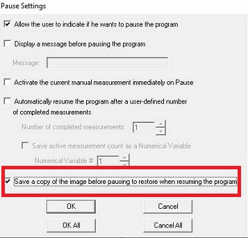
Program Toolbox – “Pause” Settings
A new option has been added to the “Program Toolbox – Pause” step settings to allow saving the current image in the program before pausing and restoring that image when the program resumes. This option is enabled by default. Disabling this option would use the current image at the time the program is resumed (if the image changes while the image is paused…)
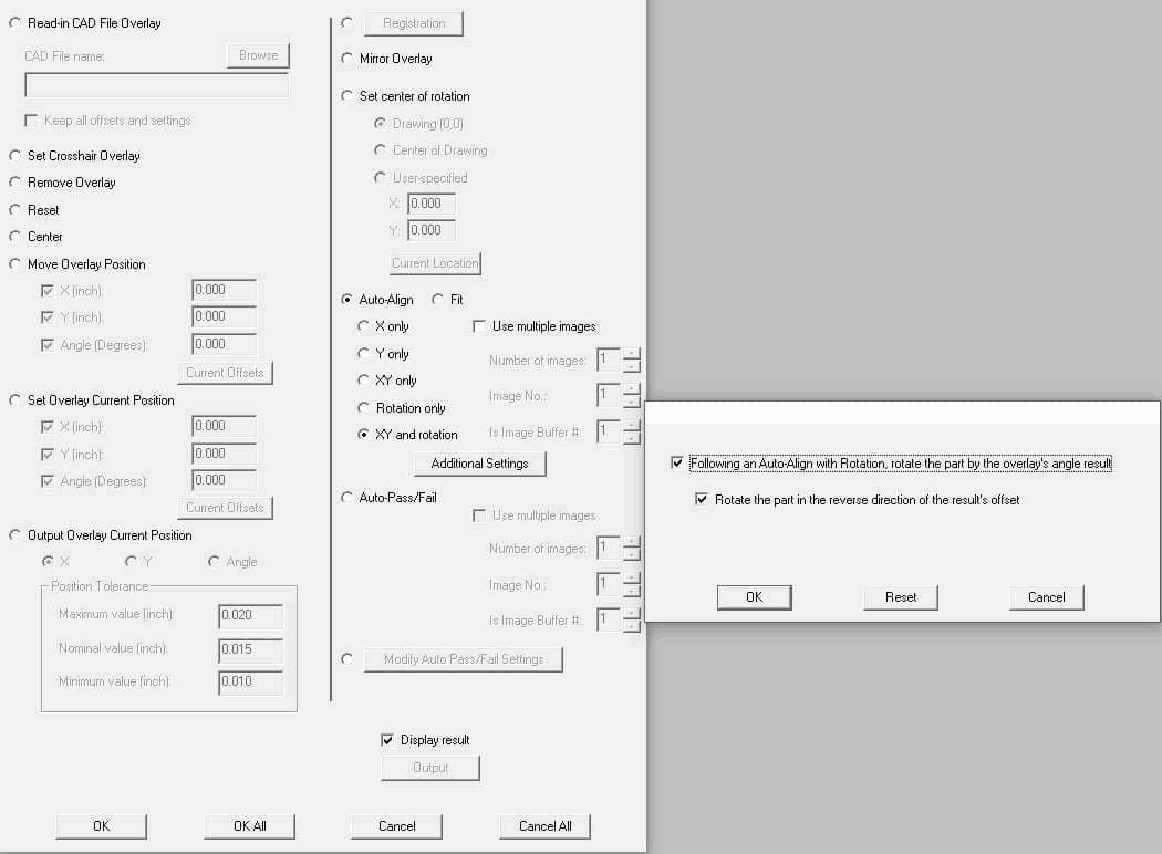
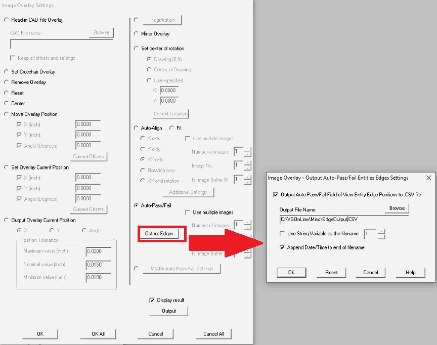
Program Toolbox – Image Overlay Settings
Additional Settings have been added to the “Program Toolbox – Image Overlay” step for an Auto-Align operation. These settings only apply to certain systems that have been setup with axes for part rotation. In this configuration, users can now choose to follow-up an Auto-Align step by rotating the axis controlling part rotation by the amount of the offset of the Auto-Align step result.
We have also added an option in the “Program Toolbox – Image Overlay” step to allow output to CSV file of the X,Y position of the located edges from the Auto-Pass/Fail operation on Entity cross sections. All Entity cross section edges located in the current field-of-view are output to the CSV file. The output file name is able to be configured by the user manually or by using a stored string variable. It is also possible to add a time/date string to the end of the filename at the time of output.
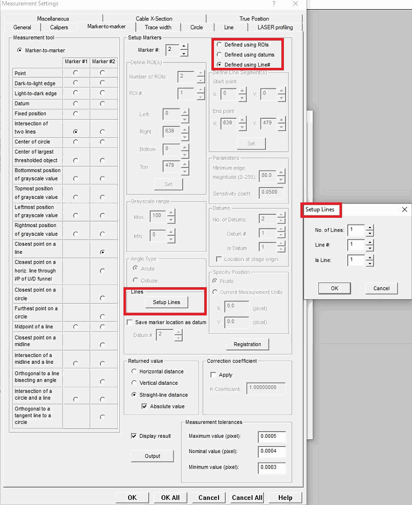
Expanded support for defining measurements using Line datums
We have expanded support for Line measurements in manual and automated measurements in the latest version of VisionGauge® OnLine. These enhancements allow operators to use the “Line Finder” and “Edge Break” measurement tools to save a located line as a Line datum (similar to our Datums), and then re-use these “Lines” in future measurements. As with Datums, these Lines travel with a part as the stage moves, such that a Line defined on the edge of a part still references the same edge as the part moves along the stage. For some measurements, previously only a single Line was able to be defined for measurements, and now we allow multiple lines to be defined to support more complex measurements.
Setup of these measurements can now select Define Using Lines to enable options to define which Lines to use. Measurements supporting definition using these Line datums include:
General Measurements:
“2-point” angles measuring from horizontal or vertical – requiring 1 Line
“4-point” angles measuring between two lines – requiring 2 Lines
Marker-to-Marker Measurements:
Intersection of 2 Lines – requiring 2 Lines
Orthogonal to a Line (or Closest Point on a Line) – requiring 1 Line
Orthogonal to a Line Bisecting an Angle – requiring 2 Lines. This measurement can now also be defined with standard Datums, too.
We have also included an option when using the Line Finder and Edge Break tools to apply iterative sub-pixel refinement which can greatly improve the resulting Line along imperfect edges.
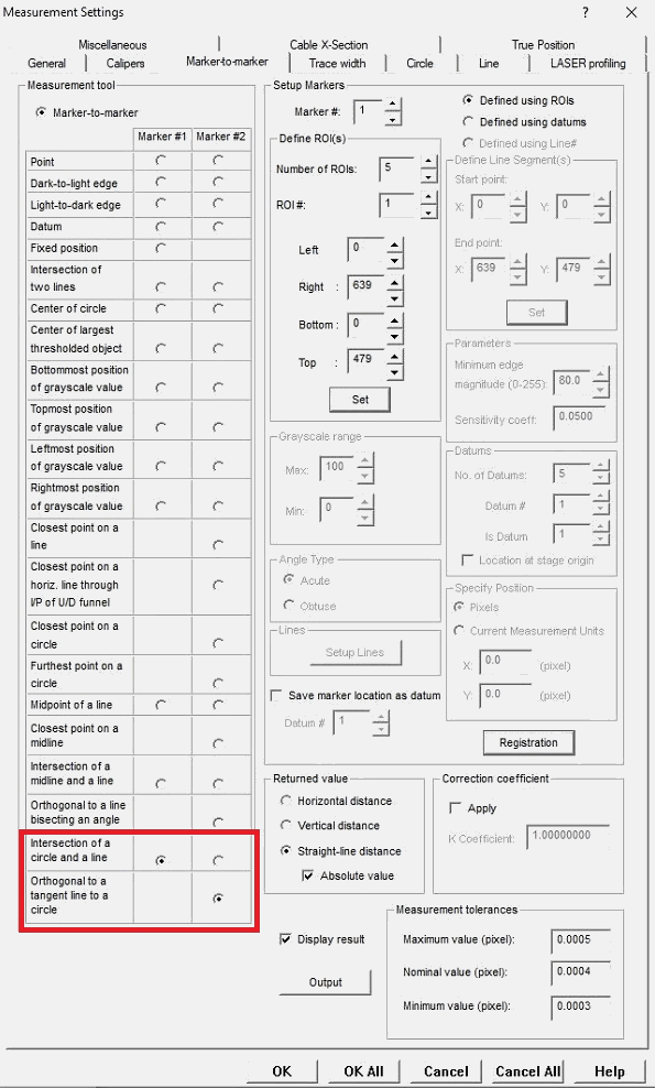
Intersection of a Circle and a Line Projection & Orthogonal to a Line Tangent to a Circle Measurements
This update adds 2 more automated measurements to the Program Toolbox – Measurement step. The Marker-to-Marker measurements now include “Intersection of a Circle and a Line Projection” and “Orthogonal to a Line Tangent to a Circle”, which were previously introduced to the manual measurement mode.
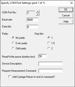
RS-232 COM Measurement Device Support Added
Support has been added to allow measurements from RS-232/COM devices (or those with USB adapters that create a COM port in Windows). When starting VisionGauge® OnLine with this update, the user will be prompted if they want to support any of these devices.
During configuration, the RS232/COM device parameters must be entered for each device, including bit rate, data bits, parity, stop bits, a device description, and the command to request a measurement from the device.
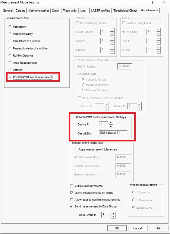
A new option for RS-232/COM Port Measurement has been added to the “Miscellaneous” tab of the manual measurement mode, as well as the Program Toolbox – Measurement step. During this setup, users need only select the number of the device they setup.
During manual measurement mode, simply pressing the Measure button will obtain the reading from the device and send it to a Data Group accordingly.
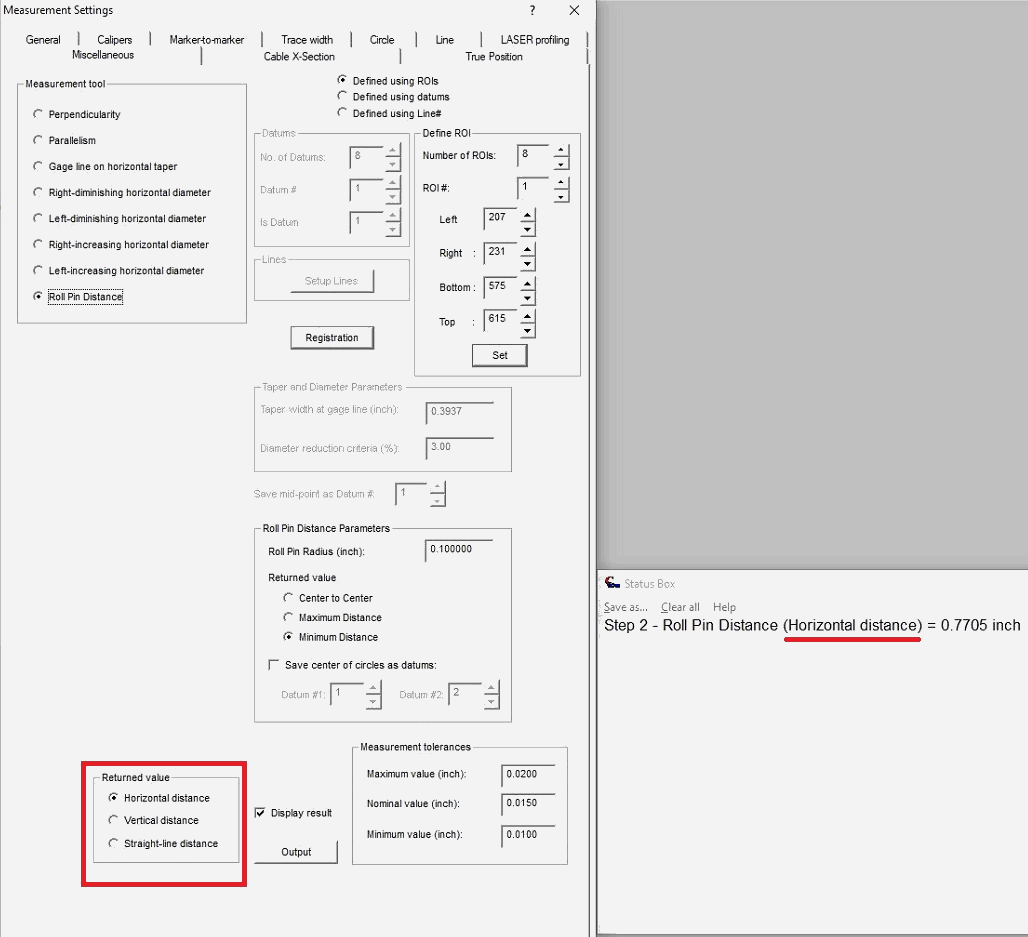
Roll Pin Distance Returned Value update
We have added a “Returned Value” option in the Program Toolbox for “Roll Pin Distance” measurements. As with other measurements that support it, this permits the user to determine if the straight-line distance is returned between the measurement points or only the horizontal or vertical component of this distance.
We have also added clarification to the measurement string returned about which value is selected. The same adjustments have been made to the manual measurement mode for Roll Pin Distance, referred to as “Primary Measurement”.
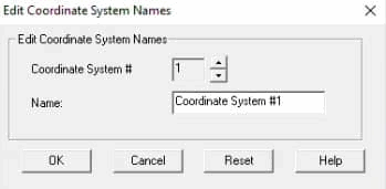
We have added the ability to edit the Motion Control Toolbox’s list of System Coordinate names. By default these are named “Coordinate System #X” for each label, up to 20 coordinate systems. At the bottom of the System Coordinate menu, users can now access a dialog box to edit these names. The names will carryover from session to session of the software.
We have enhanced the software to accommodate recent hardware changes to our newer ethernet motion control drives. Existing system with drives in this configuration will remain unchanged, except the software will startup faster than before.
We have added a 1-second wait after a stage has been instructed to home to allow the motion control system to settle after the last movement before setting the position to zero for greater positional accuracy when applying 2D XY Stage Corrections.
To protect against lost software settings when Windows is shutdown or restarted while VisionGauge® OnLine is still running, VisionGauge® OnLine will now signal that it is still running and object to shutting down Windows before the software is properly closed. If a Windows shutdown event forces VisionGauge® OnLine to close without saving the current settings, the user will be notified about the event upon startup of the following session and the last properly saved settings will attempt to be used. Examples of such shutdown events are Windows automatic updates, users logging off, and other manual or automatic restarts. As a reminder, it is highly recommended to shut down VisionGauge® OnLine properly before initiating a Windows reboot, shutdown, or user log-off operation.
We have added a notification for users when attempting to read in a newer version of Control Section or Entity-Based Auto-Pass/Fail files. The same notification is also now available for setup files. This may prevent certain crashes users experience when reading in unsupported files, particularly when sharing files between systems that do not have the same software revision.
We have expanded support for input/output of rotary stage coordinates in the Degree/Minutes/Seconds format. These units can be selected as usual from the “Settings – Units” menu. Various locations in the Motion Control Toolbox, Program Toolbox, and output have been updated with this support.
We’ve carried various performance enhancements and user interface quality improvements.
The following fixes have also been made:
We have corrected an issue where the manual measurement mode could be switched during an active measurement operation, which could cause a software crash with certain measurement types.
We have corrected an issue where the software used the wrong value when outputting the overlay’s rotation position to a Data Group from the “Program Toolbox – Image Overlay” step.
We have corrected an issue when recalling an overlay through a Data Group may change the units to ‘pixels’ if images are being collected in the Data Group. Also recalling an overlay through a Data Group previous might not have properly displayed edge search ranges for Auto-Pass/Fail entities.
We’ve corrected an issue where certain .dxf files may appear to read properly, but would display no entities or only text entities overlapping each other.
We’ve corrected an issue that may happen intermittently when manually starting an Auto-Align operation in the Overlay Translation/Rotation window. In those instances, the Auto-Align may appear to start but finishes immediately without actually moving the overlay: Pressing the button additional times results in the Auto-Align operation starting and completing as intended. This has been resolved and operates as intended on the first button press.
Previously Data Groups that had the option to restore overlays and offsets enabled were unable to properly restore the overlay when a result was populated by an automated program. This has been resolved and overlays are restore no matter how the result was populated.