VisionGauge�
Latest Enhancements
We are continuously
working to improve VisionGauge�. Here is an
overview of
the main improvements and new features that have been added to
VisionGauge�
recently:
Added in version
8.65 (dated October 1st 2007)
:
-
In VisionGauge(r)'s "Settings"
sub-menu, we have added a
new “Image Display Settings” option that allow you to reduce the
displayed
image size (even though the entire image is still kept in memory). This
can be extremely useful when working with very large images. This new
functionality
is available with PIXCI D/CL framegrabbers, DirectX-compliant video
acquisition
devices, as well as with the FlashBus Spectrim and PIXCI SV5
framegrabbers
(as well as when using no framegrabber).
-
In the "Settings | General
Preferences" window, we have added
a “Measurement Line Thickness” parameter. This new parameter can be
very
useful when used in conjunction with the previous enhancements (i.e.
when
viewing images at a reduced resolution).
-
In VisionGauge�'s Live Image
Overlay Builder, we have
added the ability to superimpose an overlay file on top the existing
overlay.
This can be very useful to allow users to superimpose multiple overlays
of different colors, for example.
-
We have improved VisionGauge�'s
support for the LUDL
motion controllers, especially for matters having to do with the Z-axis
and also the application of the convergence criteria.
-
We have added support for the
latest PIXCI framegrabber drivers.
-
We've updated VisionGauge�'s
support for the latest SPOT
camera drivers
-
We have updated the F1 Help so
that it reflects all of the
new features and enhancements in the software.
-
We have also updated the printed
User's Guide as well as
the "pdf" version of the User's Guide so that they reflect all of the
new
features and enhancements in VisionGauge�.
Added in version 8.18
(dated August 29th 2006)
:
-
We've enhanced VisionGauge�'s
support for DirectX-compliant
cameras. Specifically, we have resolved a problem where image
"freezing"
could be very slow on certain computers with DirectX-compliant cameras.
-
When carrying out diameter
& radius measurements, a marker
is now displayed in the center of the circle .
-
We've also added the ability to
save the measurement mode's
"angle quadrant" information to the Measurement toolbox. Previously,
this
information was not being saved.
-
We've also carried out a number
of other small miscellaneous
enhancements...
Added in version 8.07
(dated April 10th 2006)
:
-
We've updated the "pdf" format
documentation that
can be found in VisionGauge�'s \doc\ sub-directory.
-
We've updated VisionGauge�'s "F1
Help".
Added in version 8.05
(dated March 13th 2006)
:
-
We have added support in
VisionGauge(r) for the QImaging
Retiga 4000R FAST camera. .
-
We have enhanced support for
QImaging Retiga anmd QICam cameras
to increase the framerate of monochrome cameras and those color cameras
that support post-processing.
Added in version 8.03
(dated March 3rd 2006)
:
-
We've enhanced our support for
emailing the image directly
from within VisionGauge�.
-
We've added support
for the latest Sentinel Hardware
security key drivers. This will resolve conflicts on certain newer
computers.
-
We've added support for the EPIX
PIXCI� E1 PCI Express
x1 framegrabber for CameraLink™ cameras.
-
We've added support for the
latest SPOT camera drivers.
Added in version 7.98
(dated December 14th 2005)
:
-
We've added support for the
QImaging QICam Digital Cameras.
-
We've carried out some
improvements having to do with the
tracking of DXF-format CAD file live image overlays in the stage-based
configurations of VisionGauge�.
-
In the Motorized Stage
Configuration of VisionGauge�,
we've added a "Scan" tool that you can use to scan a user-defined area.
Note that it is possible to Pause & Resume scans and that it is
also
possible to modify the Z position following a Pause/Resume operation.
-
We've enhanced VisionGauge�'s
support for DirectX-compliant
devices.
-
VisionGauge� now displays a
"Range" value (range = max
- min) in the "Statistics" section of the Numerical Data Groups.
-
We've added support for the
latest PIXCI framegrabber drivers.
-
In the stage-based
configurations of VisionGauge�, we've
carried out enhancement having to do with setting an arbitrary position
in the presence of stage XY squareness correction.
Added in version
7.94 (dated August 19th 2005)
:
-
We've added support for
the SPOT Flex(tm), Pursuit(tm) and Xplorer(tm) digital cameras.
-
We've enhanced our support
of the SPOT Insight(tm) and Insight QE(tm) digital cameras.
-
We've added support for the
latest SPOT camera drivers.
-
We've enhanced our support for
DirectX-compliant video acquisition
devices (such as the Lumenera cameras). Specifically, we've carried
out
enhancements that are useful when working with very large images as
well
as improvements to the support for live image overlays.
Added in version
7.89 (dated May 31st 2005)
:
-
VisionGauge(r) now has support
for its full Live Image Overlay
Toolset when using DirectX video capture devices (such as Lumenera
cameras).
-
VisionGauge(r) now has support
for its full Live Image Overlay
Toolset when using the QImaging Retiga & QImaging
MicroPublisher cameras.
-
In VisionGauge(r)'s "Settings |
General Preferences" menu
option, we've added a "Number and Increment Quick Save Images"
checkbox.
By default, it is checked. When this is the case, a number is added to
the QuickSave filename and this number is incremented. When this
checkbox
is not checked, on the other hand, the quicksave image is simply saved
with the file name and extension specified. If these parameters are not
changed between QuickSave operations, the previously saved image will
be
overwritten (without the user being notified).
-
We've added support for the
latest SPOT camera drivers.
-
We've carried out a number of
small enhancements to the "Data
Groups" tool, as well as to their ability to "Automatically Export Data
to Excel".
Added in version 7.83
(dated March 23rd 2005)
:
-
We've added Data Groups
tools to VisionGauge(r).
Data Groups
allow you to automatically collect measurements and to group them as
you
please. Statistics are also automatically calculated. Typically, Data
Groups
are used to group together "like" measurements.
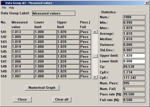
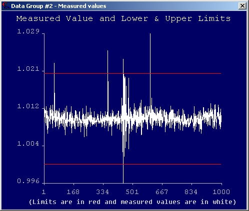
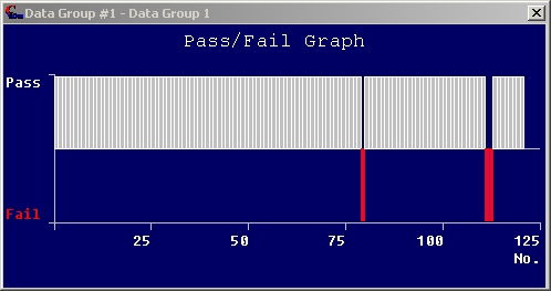
Data Groups
also allow you to automatically create charts & graphs of your
data
(both numerical & pass/fail):
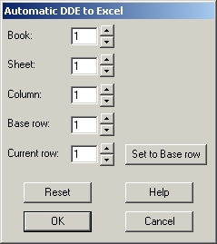
You can also
use Data Groups to automatically export measurements to Excel:
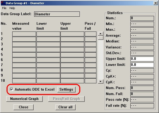
You can specify
the Excel Book & Sheet numbers, as well as the base row
& column,
through the "Settings" button:
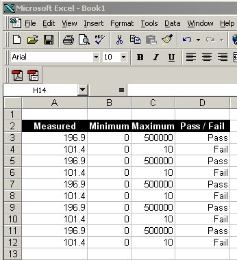
All of the
data going into the Data Group will then also automatically be sent to
Excel, i.e.:
In the Motorized
Stage Configuration of VisionGauge�, you can send measurements to Data
Groups by specifying, in the appropriate lineof the
program, if
a measurement is to be sent to a data group, and to which.
You can also send
measurements to Data Groups through the Program Toolbox, once again by
providing the relevant information in the
appropriate line
in the program.
Finally, please
note that we've also added the ability to remove data from a Data
Group,
using the "Remove" button.
Data Groups can be
setup and accessed through the "Data Groups" menu option found in the
menu
of the main VisionGauge(r) window.
-
We've made the "Display
Message" edit box in the Program Toolbox scrollable, so that you can
enter
longer message strings to display...
-
We've carried out small
"display" improvements with VisionGauge�'s Live Image Overlay Builder,
when reading-in DXF format CAD files and
using the "Based
on Calibration" scaling.
-
We've carried out small
enhancements to the calibration toolbox (i.e. the edit box
automatically
gets the focus when you want to store a calibration
in a
button)
-
We've added a menu option
in the "Command" sub-menu to "View the measurement report".
Added in version 7.77
(dated January 31st 2005)
:
-
We've added the ability to
change the video input format
when using a DirectX video acquisition device.
-
We've added a "Stop immediately
on Pause" checkbox in the
Motion Toolbox's "Settings" window. When you select this checkbox, the
stage motion stops as soon as you press the "Pause" button. When this
checkbox
is not selected, the stage's motion is only stopped once the current
step
or operation is completed.
-
We've added a checkbox in the
Motion Toolbox's "Settings"
window that you can use to indicate to the software that the user
should
be asked to supply a text string when the Motion Toolbox's "Output"
button
is pressed. The user-supplied text (it could be a single character,
multiple
characters, or no characters at all) will be written to the Data File,
on the same line as the stage position, at the end of the line.
-
We've carried out a number of
small enhancements when using
DirectX video acquisition devices.
-
We've added information about
the renewal date of the "VisionGauge�
Annual Support and Update Program" in the "Help | About" dialog box...
-
We've updated the html-format
"F1 Help".
-
We've update the "pdf" file
containing the electronic format
documentation that comes with VisionGauge�.
-
We've moved the "Pause" button
away from the Stop button
in the Motion Toolbox (to prevent accidental "Stops" instead of
"Pauses").
-
We've added the following
"hotkeys" in the Motorized Stage
Configuration of VisionGauge�
F5 : Pause / Resume
F6 : Output
Added in version
7.71 (dated November 4th 2004)
:
-
We've added a "Pause /
Resume" button in the Motorized Stage Configuration of VisionGauge�.
This button can be used to pause a program being run in either
"Continuous"
or "Automatic" mode.
-
We've added support for
the latest SPOT Camera drivers.
-
We've carried out some
miscellaneous enhancements to the
"DXF Live Image Overlay With Stage Motion Tracking"
Added in version 7.66
(dated October 6th 2004)
:
-
We've added native support for
the QImaging(tm) MicroPublisher
cameras
-
We've enhanced VisionGauge(r)'s
multi-camera support when
using the FlashBus Spectrim video acquisition card.
-
We've added the ability to carry
out live previews when changing
the device-dependent settings for all DirectX-compliant video
acquisition
devices (including the Lumenera cameras).
Added in version 7.63
(dated September 7th 2004)
:
-
We've added enhanced support for
large-format DirectX capture
devices (including the Lumenera cameras)
-
We've carried out some
enhancements to the "Counting &
Sizing" tool, to optimize performance when working with very large
images.
-
We've added enhanced support for
the latest PIXCI video acquisition
board drivers from EPIX INC. (i.e. PIXCI SV5, PIXCI D, PIXCI CL,
etc...).
-
We've improved Full Screen Live
Video support when using
the FlashBus Spectrim, so that it is guaranteed to work on all computer
& operating system configurations.
-
We've added extended support for
Live Image Overlays when
using the PIXCI CL and PIXCI D framegrabber
Added in version 7.55
(dated July 4th 2004)
:
-
In the Program Toolbox's
"Settings" sub-menu, We've added the ability to "Buffer Data File
output
to the end of the program". This has been added for compatibility with
certain data capture and analysis programs that require that groups of
data be written to disk all at once (as opposed to one at a time, as
they
become available).
-
We've resolved some version-related
issues (i.e. made it impossible to read-in program files created with a
more recent version of the software than the one currently running)
-
We've added enhanced support
for the SPOT cameras.
Added in version 7.52
(dated April 9th 2004)
:
-
We've enhanced the "Plane-To-Point"
measurement tool so that it can now be used to measure the distance
between
a plane and many points (i.e. a user-defined number of
points).
-
We've added enhanced support
for the SPOT Insight FireWire&teade;
camera.
-
We've enhanced VisionGauge�'s
support for 8 bit
images with certain TWAIN drivers (including the QImaging QiCAM
camera's
TWAIN drivers).
-
We've added small enhancements to the functionality of the Program
Toolbox's
"Next" and "Previous" commands.
-
In both the Manual &
Motorized-Stage Configuration of VisionGauge�, we've added the ability
to set an arbitrary "current" position (i.e. not just 0, 0, 0) in the
Motion
Toolbox & the DRO.
-
In the Motorized-Stage
Configuration of VisionGauge�, We've added the ability to set a "Load
Position" in the Motion Toolbox. You can use the "Set load position"
option
in the motion toolbox's Settings sub-menu to specify the load
position.
Then, when you press the Motion Toolbox's "Load..." button the stage
automatically
goes to this position.
Added in version
7.45 (dated January 16th 2004)
:
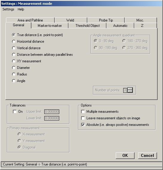
-
We've completely re-designed
the "Settings | Measurement Mode" toolbox, so that it uses "tabs" to
separate
the different measurement tools into logical tools. This makes the
toolbox
much easier to navigate.
-
We've added support for
DirectX-compliant video acquisition
devices (i.e. IEEE 1394 / FireWire(tm), USB 2.0, etc...)
-
We've added support for a new
PCI-bus card for computer-controlled
illumination that supports up to 4 light sources.
-
We've added an option - in the
Program Toolbox's "Settings"
menu - to specify that a data file should automatically be
opened
when a program is started and closed when the program is stopped. The
user
can specify the name & location of the data file. This
information
is saved with the program itself. This means that each program can be
associated
with a unique data file, for example, or that this option can be turned
on for some programs and off for others.
-
We've enhanced VisionGauge�'s F1
Help. Also, the F1 Help
is now in a new up-to-date HTML format.
-
We've added support for the
latest SPOT camera drivers
-
We've made the edit box for the
QuickSave file name
(in the "Settings | General Preferences" menu) "scrollable".
This
allows the use of longer filenames as well as the inclusion of path
information,
etc...
-
We've carried out some minor
enhancements having to do with
image capture using the FlashBus MX / DX boards.
-
We've carried out some minor
enhancements having to do with
Joystick-based motion, in the motorized stage configuration of
VisionGauge�
(resulting in even finer motion control).
Added in version 7.34
(dated October 16th 2003)
:
-
New "Noise Removal" and
"Uneven Illumination Correction" Image Processing tools that are very
useful
to "clean-up" images that cannot be properly dealt with by the image
analysis
tools and transform them into imagery that can be successfully analyzed
reliably. Here is an example:
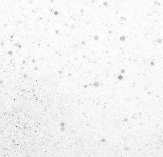
Original image

Results of image analysis on the original image.
We see that it is impossible to apply a unique threshold
value across the entire image to successfully extract
the objects from the image background.

Results of image analysis after noise reduction and uneven illumination
correction.
In this case, the objects can be separated easily &
reliably
from the image background after applying VisionGauge's�
noise reduction & uneven illumination correction tools.
For more information, please follow this link:
https://www.visionxinc.com/software-systems-machines/image-processing-for-image-analysis.pdf
-
We've also added an Image Processing tool for "Image Blurring".
-
We added a "Ctrl-N" hotkey to quickly call-up the Annotation Toolbox.
Added in version 7.31
(dated September 22nd 2003)
:
-
We've added the "Ctrl+W"
hotkey to open the "Zoom & Focus Control" window.
-
We've extended VisionGauge's�
DDE support so that all of the data in VisionGauge's� built-in report
generator can also be sent to other applications using DDE. To query
VisionGauge�
for any "Report" data, the "topic" keyword is Report and the Item
keywords
are the following:
- Key1, Key2,
- Text 1 through Text10
- Date
- Meas1 through Meas10
and
- Comment1 through Comment10
-
We've extended VisionGauge�
HT's (i.e. for Hardness Testing) DDE support so that all of the
Hardness
Testing-specific data can also be sent to other applications using DDE.
To query VisionGauge� for any "Hardness Testing" data, the "topic"
keyword is HardnessTesting and the Item keywords are the following:
- VickersLoad
- VickersFirstDiagonal
- VickersSecondDiagonal
- VickersMeanDiagonal
- VickersDepth
- VickersHardness
- VickersRockwell
- BrinellBallDiameter
- BrinellTestForce
- BrinellMeanIndentationDiameter
- BrinellHardness
- KnoopLoad
- KnoopLengthOfLongDiagonal
- KnoopHardness
- KnoopRockwell
-
We've enhanced VisionGauge's�
support for "TIFF" image files.
-
We've carried out a Marker-to-marker
measurement "Drawing bug fix" in the case where Marker #2 is a the
center
of a "thresholded object" and Marker #1 is not. In this case, Marker 2
(the thresholded object) previously did NOT get displayed properly
(although
it did get computed properly). This has now been corrected.
Added in version
7.29 (dated August 30th 2003)
:
-
We've updated the User's
Guide. The up-to-date version of the Visiongauge(r) User's Guide is
available
in "pdf" form in the "\doc\" sub-directory.
-
When the Computer-Controlled
Illumination feature is enabled, VisionGauge� now automatically turn
the lights off when you exit the software. This promotes longer lamp
life.
-
We've enhanced the "Click
to center" tool in the Motorized Stage Configuration of VisionGauge�.
-
We've fixed a problem
with the area distribution curve output through the "File | Save as..."
menu command in the Counting & Sizing tool.
Added in version 7.25
(dated July 25th 2003)
:
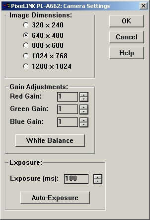
-
We've added Exposure &
Auto-Exposure controls to VisionGauge�
when using PixeLINK PL-A662 cameras. The camera control windowfor the
PixeLINK
PL-A662 is now the following:
-
We've enhanced calibration
password protection so that it
now also applies to the "Command | Calibrate" menu option.
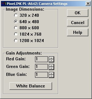
-
We've enhanced support for the
PixeLINK PL-A662 & PL-A642
Cameras (i.e. the image stays centered at all of the different
supported
resolutions).
-
We've added support for the
latest SPOT camera drivers (i.e.
version 3.5.9, dated July 22nd 2003).
-
We've carried out a few minor
"Counting & Sizing" enhancements.
Added in version 7.19
(dated May 9th 2003)
:
-
With the Motorized Stage
Configuration of VisionGauge�,
it is now possible to click on a feature with the mouse to bring it in
the center of the field-of-view. This feature can be enabled by
checking
the "Click on a feature to center it in the FOV" checkbox in the Motion
Toolbox's "Settings | Motion Control" window.
-
In the stage-based editions of
VisionGauge� (i.e. both
the Manual- and Motorized-Stage Configurations), it is now possible to
skew a DXF-format CAD overlay that is set to "track" the stage's
motion.
To do this, simply set the part's skew, goto to the part (0,0) position
and read-in the DXF-format CAD file.
To use this feature:
1) in VisionGauge, choose
the same units as the units
in the DXF format cad file (i.e. if the drawing is in mm, choose mm in
VisionGauge)
2) make sure that
VisionGauge is properly calibrated optically
3) set the part "zero"
(i.e. go to the "zero position"
with the stage and press "Set Zero" either in the "DRO" window or in
the
Motion toolbox" window)
4) set the part's skew
(through the "Command | Skew part"
menu in either the "DRO" window or in the Motion toolbox" window).
5) go to the part's zero
position.
6) Open VisionGauge's
Live Image Overlay Builder (through
the "Settings | Live Image Overlay" menu option and then press the
"Overlay
Builder" button).
7) In VisionGauge's Live
Image Overlay Builder, choose
"File | Read-in CAD file".
8) Pick the appropriate
file.
9) Then choose a scaling
"based on calibration" and check
the "track with stage motion" checkbox.
The DXF overlay will be
drawn in such as way as its "zero"
position matches up with the part's zero position and it is skewed
along
with the part. Also, the overlay will "move" with the stage...
Added in version 7.17
(dated April 21st 2003)
:
-
We modified the "Settings |
Measurement Mode" window to be
compatible with low resolution display settings.
-
We added a "rectangular grid"
stage mapping function in both
the Motorized- and Manual-Stage configurations of VisionGauge�.
-
We sped-up VisionGauge's�
Auto-Mosaic tool.
-
We've added support for the
latest SPOT camera drivers.
Added in version 7.15
(dated April 1st 2003)
:
-
We've added support for version
3.x of the drivers for the
PixeLink PL-A642 FireWire Digital camera.
-
We've added support for the new
PixeLink PL-A662 FireWire
Digital camera.
-
We've added support for the
latest SPOT camera drivers.
Added in version 7.14
(dated March 27th 2003)
:
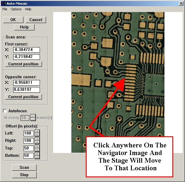
-
We've added a Mosaic-Based
Navigation Tool to the Motorized-Stage
Configuration of VisionGauge�. This new feature is part of the
Auto-Mosaic
tool. To enable the Navigator, simply select "Navigator" in the
AutoMosaic
tool's "Options" sub-menu.
With the new Navigator tool, you
start by building
a mosaic of a portion of your stage's travel. But contrary to the
AutoMosaic
builder, the Navigator uses very little memory, so you shouldn't feel
that
you have to limit the area to consider. Then, once the mosaic is built,
just click anywhere on the mosaic image (which constitutes a
"navigation
map") and VisionGauge's� Navigator tool moves the stage so that the
point that you selected is brought under the optics.
Hint:
you can relax the "Convergence Criteria"
in the Motion Toolbox's "Settings | Motion Control" window to speedup
the
process of building the mosaic image.
- We've added "Pass /
Fail" buttons in VisionGauge's� Motion
Toolbox. You can use these buttons for simple operator-assisted visual
inspection programs. These buttons send a "Pass / Fail" result to the
Measurement
Report and move forward in the program. Note that on "Pass" we move to
the next line in the program, whereas on "Fail" it is possible to
instruct
VisionGauge� to advance by more than one step in the program. This
is done, at any step in the program, using the new "Number of steps to
advance on Fail" option. This is useful, for example, if we want to
disregard
all of the other inspection steps that consider a given device as soon
as we find one defect on the device.
-
It is now possible to read-in to
the Motion Toolbox ASCII
data in many different formats: XY, XYZ, XY + Label and XYZ + Label.
When
you read ASCII data into the Motion Toolbox, VisionGauge� prompts you
at the appropriate time and asks you to indicate the file format.
Added in version 7.12
(dated March 17th 2003)
:
-
VisionGauge� now has three
measurement tools that are
specifically designed for the measurement of welds (i.e. to measure the
weld legs, throat, root, etc...).
-
We've enhanced VisionGauge's�
"Marker-to-Marker" measurement
tool and added a new type of marker: the point of intersection of two
lines.
-
We've added "stretching"
coefficients along both the X- and
Y-axis directions. These coefficients can be accessed through the
"Settings
| Units | Advanced" menu option.
Added in version 7.10
(dated February 28th 2003)
:
-
In both the Manual- and
Motorized-Stage Configurations of
VisionGauge(r), a DXF-format CAD overlay can be made to follow the
stage's
motion. This ability to have the live image overlay "track the
part"
allows you to carry out inspections and compare the part with its CAD
drawing
at higher magnifications.
-
It's now possible to carry out
measurements on a live image
with both the FlashBus Spectrim and FlashBus MV framegrabbers.
-
We've added support for both the
AutoFocus & Focus Meter
tools with the FlashBus Spectrim framegrabber
-
We've added support for the
latest SPOT camera drivers
-
We've added two new
"Perpendicularity Correction Factors"
that you can use to correct for any perpendicularity error between the
column & the stage in a stage-based system (either manual or
motorized).
Added in version 7.09
(dated February 17th 2003)
:
-
We've added support for the
Integral XPress family of framegrabbers
as well as for the new Integral FlashPoint 4XL framegrabber. For a
complete
list of the video acquisition devices supported by VisionGauge, please
consult FAQ #1.2 in the "Frequently Asked Questions" section of our web
site.
-
With the Integral FlashBus
Spectrim, we've added support
for the "Video Sequence Capture" tool.
-
It's now possible to carry out
stage-based measurements with
any type of live image overlay, or even without a live image overlay.
-
We've enhanced VisionGauge�'s
"Arbitrary Image Rotation"
tool. It now uses higher-order interpolation, thus producing a
resulting
image with a better appearance.
-
In the motorized stage
configuration of VisionGauge�
we've enhanced the AutoFocus tool and made it significantly faster.
-
We've added new "checkboxes" in
both the "Motion Tollbox
Settings" window & the "Program Toolbox Settings" window that
allow
users to automatically clear the statistics toolbox and / or the
measurement
report when a program is started.
Added in version 7.01
(dated January 17th 2003)
:
-
We've enhanced VisionGauge� so
that the "Live Image Overlay
Builder with Support for *.dxf Format CAD Files" works with the new
FlashBus™
Spectrim framegrabber.
-
We've disallowed simultaneous
"Next" and "Previous" commands
when running operator-assisted programs in the Motorized Stage
Configuration
of VisionGauge�.
-
We've carried out some
enhancements to VisionGauge's�
stage motion sub-routines in the case where a system has a non-encoded
motorized Z axis.
-
We've resolved a conflict that
occurred in VisionGauge's�
Counting & Sizing tool when an operator attempted to select an
object
on the tool's startup, and no object had yet been thresholded.
Added in version 7.00
(dated January 7th 2003)
:
-
We've added support for the
FlashBus(tm) Spectrim framegrabber.
For an up-to-date list of all of the video acquisition devices that
VisionGauge�
supports, please see FAQ #1.2 in the Frequently Asked Questions section
of our Web Page.
-
We've added a "Program Toolbox"
that you can use to record
& playback a series of instructions. You can access this new
Program
Toolbox through the Command sub-menu in the main VisionGauge� window.
Here's a "screen
capture" of the Program Toolbox's
interface:
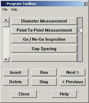
In this example,
the program contains only 4
simple instructions. Each instruction corresponds to a button in the
Program
Toolbox. There is no limit on the number of instructions in a program.
The scrollbar on the left of the Program Toolbox allows you to scroll
through
long programs and the white arrow on the right points to the current
instruction
in the Program.
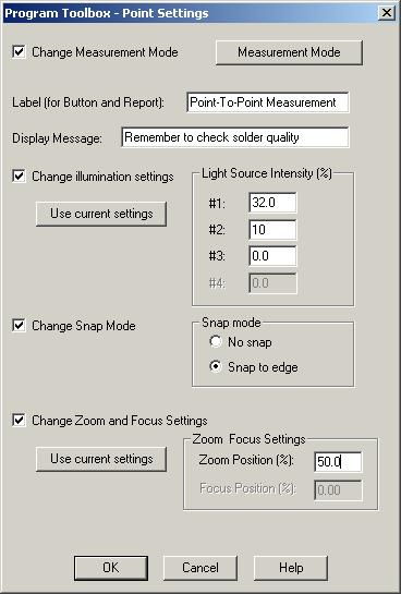
You can add &
modify instructions by simply pressing
on the appropriate button. When you do this, a window such as the one
below
appears. You can use this window to set the instructions that need to
be
carried out by VisionGauge� at this point in the program.
Please note that Programs
can be saved to disk and then
read-in & played back later on. Also, the Program Toolbox data
can
be password protected, using the "lock-out" password protection
described
in the VisionGauge� User's Guide.
To start running a
program, you use the Program Toolbox's
"Run" button. The "Next" and "Previous" buttons allow you to step
through
a program and the "Stop" button allows you to stop it.
You can use the "Insert"
and "Delete" buttons when you
are editing a Program and you want to either insert or delete
instructions.
Finally, please note that
this new Program Toolbox is
available in all of the Editions of VisionGauge�.
Added in version 6.99
(dated December 20th 2002)
:
-
We've added support for 8 bit
per pixel (i.e. grayscale)
bitmaps image files.
-
We've added support for updated
drivers for the SPOT cameras.
-
We've added support for updated
drivers for the FlashBus
MX & FlashBus DX framegrabbers
-
In the Motorized-Stage
Configuration of VisionGauge�,
We've added the ability to give the command to "Keep Z constant" at one
or many points in a program. You would include this command in a
program
after you have used the AutoFocus tool to find a point's Z position and
you know that one or many points that follow are at the same Z
elevation.
In this case, you wouldn't have to AutoFocus at the following points
because
the z position would be kept constant.
-
In the Motorized-Stage
Configuration of VisionGauge�,
We've added the ability to "zero out" one or many of the axis at one or
many points in the program. You could use this, for example, for a
program
involving many different parts.
-
In the Motorized-Stage
Configuration of VisionGauge�,
We've solved certain joystick-related conflicts under Windows 2000
-
In the Motorized-Stage
Configuration of VisionGauge�,
We've added support for variable illumination in the AutoMosaic tool
(i.e.
the illumination intensity is interpolated along the Y axis).
Added in version 6.94
(dated November 7th 2002)
:
-
We've added support in
VisionGauge� for the most recent
drivers for the PixeLINK PL-A642 FireWire(tm) (IEEE 1394) digital
camera.
.
-
In both the Manual and Motorized
Stage Configurations of
VisionGauge�, We've added a correction factor
that allows
you to correct "Stage Squareness" error. To use this correction factor,
simply create an ASCII text file called "VisionGauge.sqr" in the main
VisionGauge�
sub-directory (typically: "c:\VisionGauge\"). You can use a simple text
editor such as (Microsoft NotePad) to create this file. In this file,
put
the value of the stage squareness correction coefficient. This
correction
coefficient is simply the negative of the "delta x" deviation that can
be observed over a travel of "delta y", due to stage squareness. For
example,
if the stage squareness error causes an error (delta X) of 4 microns
over
a distance (delta Y) of 200000 microns, then the value of the stage
squareness
correction coefficient is -0.00002.
Added in version 6.93
(dated November 5th 2002)
:
-
We've added support in
VisionGauge� for a Video-to-FireWire
converter that can be used for notebook-based mobile systems.
-
We've added a user-prescribed
offset when reading-in dxf-format
CAD files into VisionGauge's� Live Image Overlay Builder. You can use
this offset to shift the entire drawing in both the X and Y directions.
By default, both offset values are zero and VisionGauge� aligns the
center of the CAD data in the middle of the field-of-view.
Added in version 6.92
(dated October 4th 2002)
:
-
We've added a new "XY Position
of Thresholded Object" measurement
tool. This tool can be used for both stage-based and field-of-view
measurements.
-
We've added the capability to
output measurement labels to
the "Automatic Measurement Report" during manual field-of-view
measurements.
-
We've added an option to enable
or disable the joystick (both
external and on-screen) during the execution of stage-based programs.
This
new setting can be found in the Motion Toolbox's "Settings | Motion
Control"
sub-menu.
-
We've solved certain
joystick-related conflicts under Windows
2000
-
We've updated the "Power Zoom"
algorithm in response to a
change in the controller's drivers. This results in greater positional
feedback, which in turns enhances measurement accuracy.
-
We've improved the display -
during automated measurement
programs - for certain "thresholded object" measurement tools.
Added in version 6.90
(dated September 20th 2002)
:
-
We've added support in
VisionGauge(r) for the PixeLINK PL-A642
FireWire(tm) (IEEE 1394) digital camera. You can control all of the
camera's
different settings directly from VisionGauge(r), through the following
easy-to-use window:
-
In VisionGauge(r)'s Report
Builder, it is now possible to
save images in the report database using the JPEG format. The JPEG
image
file format allows you to save space on your hard disk. However, please
keep in mind that JPEG images have been compressed and that they cannot
be used reliably to carry out high-accuracy measurements. If you think
that an image that you're saving in the report database is likely to be
used for measurements sometime in the future, we suggest that you
continue
to use the uncompressed BMP format.
Added in version 6.89
(dated September 9th 2002)
:
It's now possible to send
field-of-view measurements to the
"Measurement Report" window. Previously, only automated stage-based
measurements
could be sent to this window.
To send field-of-view
measurements to the"Measurement
Report", simply check the "Insert field-of-view measurements in
Measurement
Report" check box in the "General Preferences" window.
- In automated measurement
programs, it's now possible to tell
VisionGauge(r) that one or many points in the program is not to be used
for measurements. This can be done in the "Motion Program - Point
Settings"
window.
-
Added in version 6.88
(dated August 8th 2002)
:
-
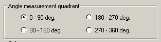
It's now possible for
you to specify the quadrant for angle measurements (i.e. 0-90 deg.,
90-180,
180-270 and 270-360 deg.). This is done in the "Settings | Measurement
mode" window.
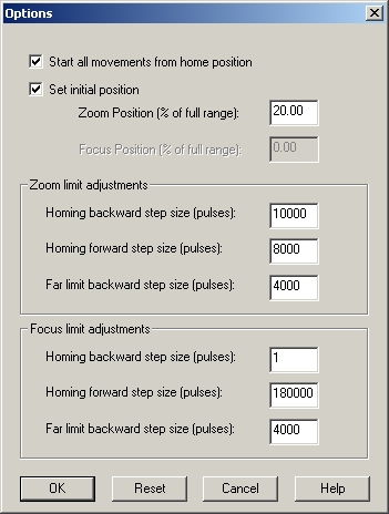
-
When using VisionGauge�
with servo-encoded motorized optics, it's now possible for you to
specify
"initial" zoom & focus settings. The optics will go to these
positions
when you startup VisionGauge�. This is done through the "Options" menu
command in the "Zoom & Focus Control" window:
-
Each character of the
password that you type in is now displayed using an asterisk (*). This
is true for both the "Calibration" password and the "Lock-Out" password.
-
We've updated the on-line
help (available through the F1 hotkey).
-
This update contains a
significatntly enhanced version of the Visiongauge�
User's
Guide (in pdf format).
Added in version 6.86
(dated June 15th 2002)
:
-
We've added support in
VisionGauge� for the SPOT INSIGHT
QE camera.
-
We've enhanced VisionGauge's
"Live Image Overlay Builder"
with DXF format CAD file support, to make it work with the INSIGHT and
INSIGHT QE cameras.
-
VisionGauge's� "Video
Sequence Capture" Tool can
now read-in AVI files.
-
We've fixed "upside down"
display problems with the FlashBus
MV & FlashBus DX video acquisition boards.
-
We've added the F4 "hotkey" that
you can use to quickly read-in
overlay files.
Added in version 6.82
(dated April 2nd 2002)
:
-
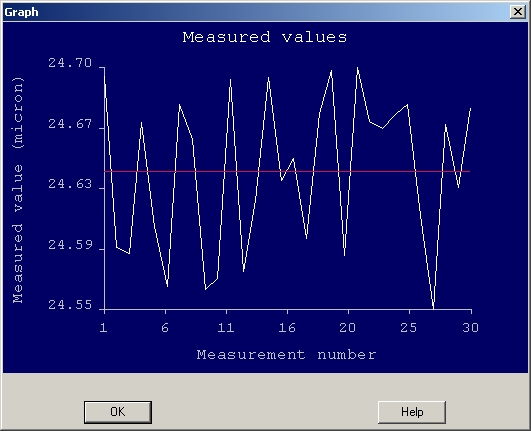
In VisionGauge's�
"Statistics Toolbox", We've added the ability to draw charts of all of
the values in a sample, as well as of the sample mean. Here's a simple
example:
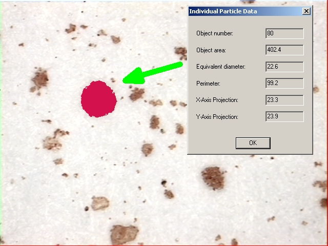
-
VisionGauge's�
"Counting & Sizing" tool can now compute, display and save to
disk
the perimeter, as well as the projections along both the X and Y axis
of
individual particles:
Added in version 6.81
(dated March 15th 2002)
:
-
We've added a new Coplanarity
Measurement Tool. This new coplanarity tool follows JEDEC standards
(i.e.
"Coplanarity Test for Surface-Mount Semiconductor Devices -
JESD22-B108"
- www.jedec.org).
-
We've fixed a problem
with the color correction & white balance support when using
the the
SPOT INSIGHT camera.
-
We've added "trigger"
support (for a footswitch, for example).
Added in version 6.79
(dated February 26th 2002)
:
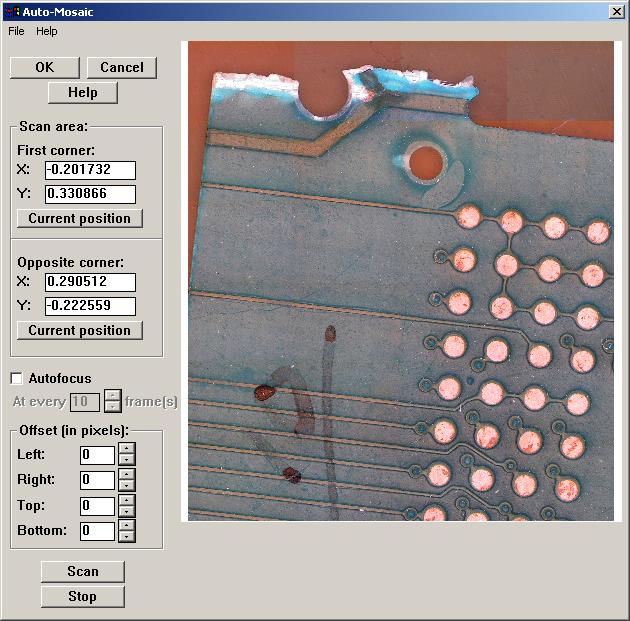
-
We've added a new "Auto-Mosaic"
Tool in VisionGauge�. This new tool allows you
to automatically
build a very high-resolution image of areas that are larger than your
system's
optical field of view.
VisionGauge's�
"Auto-Mosaic" Tool is very easy to use: simply select two opposite
corners
of the area that you are interested in and press the "Scan" button.
VisionGauge�
does everything else! You can also tell VisionGauge�
to
periodically refocus the image or ignore a certain number of rows
&
columns of pixels on each of the different borders of each
field-of-view.
This allows you to compensate for uneven illumination, for example.
Here's a picture of
VisionGauge's� "Auto-Mosaic" Toolbox:
Finally, please
note that the maximum size of the resulting image (and thus the maximum
area that you can scan at any one time) is only limited by your
computer's
system memory.
Added in version 6.77
(dated February 12th 2002)
:
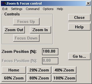
-
We've added "preset buttons"
that you can use to quickly
get to a preset zoom position, when using motorized zoom optics in
conjunction
with the VisionGauge� encoded servo-motor controller. The default
present
positions are: Home (i.e. 0% zoom), 20% zoom, 40% zoom, 60% zoom, 80%
zoom
and 100% zoom. VisionGauge's� "Power Zoom & Focus" window now
has
the following appearance:
-
You can now directly get the
"Counting & Sizing" thresholds
from within the "Settings | Measurement mode" window. This is very
useful
when you're setting thresholds for automated measurement programs, for
example.
-
We've added 2 "hotkeys": F2 to
turn Live Video ON and F2
to give the "Measure" command.
Added in version 6.74
(dated February 1st 2002)
:
-
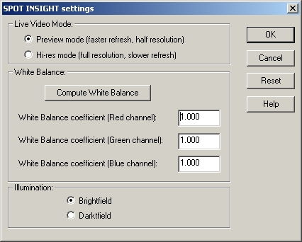
We've added support in
VisionGauge� for the SPOT Insight
digital cameras. When you use an Insight camera, VisionGauge� allows
you to access to the camera controls through this simple
interface:
-
We've added support for the
QImaging Retiga Monochrome cameras.
The complete list of video acquisition devices supported by VisionGauge�
is available in the "Frequently Asked Questions" (FAQ#1.2) section.
Added in version 6.73
(dated January 14th 2002)
:
-
We've added support in
VisionGauge� for the Integral
Technologies FlashBus DX video acquisition boards for digital cameras.
The FlashBus DX™ video acquisition boards also have a
�Camera
Link� interface and are designed to capture both RGB and monochrome
images in real-time to either system or display memory. The complete
list
of video acquisition devices supported by VisionGauge�is
available in the "Frequently Asked Questions" (FAQ#1.2) section.
Added in version 6.72
(dated January 7th 2002)
:
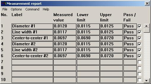
We've added a new Measurement
Report that allows you to easily
collect, manage & analyze the results of fully-automated
measurement
programs.
This new reporting tool
for fully-automated systems lets
you:
attach a label (or identifier)
to each measurement,
select individual measurements
and group measurements together
save groups of measurements to
file
send groups of measurements to
the statistics toolbox (this
is very useful for analyzing results from a measurement program in
which
you "mix & match" different types of measurements,
etc...).
This new measurement report for
fully-automated measurement
programs has many other useful and easy-to-use features and options.
For
example, the report can be displayed in either "full" or "small" format
(to save space on the desktop).
Please note that there is
no limit on the number of measurements
that this report can handle.
Added in version 6.71
(dated December 28th 2001)
:
-
It's now possible to add text
overlays in VisionGauge's�
Live Image Overlay Builder.
-
We've enhanced VisionGauge's�
camera "synching" when
using video acquisition boards from the Integral Technologies 3D
family.
This can be useful when using video sources that are difficult to synch
with (or that have low-quality synch signals) such as VCRs.
-
It's now possible to use the
"distance between arbitrary
parallel lines" tool to calibrate VisionGauge� (i.e. to compensate
for alignment errors between the calibration standard & the
camera...).
-
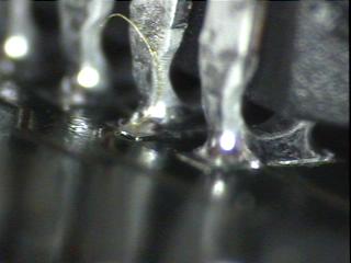
We've added 2 new measurement
tools for the automated measurement
of wire bond solder balls. You can use these new tools to carry out
automated
measurements of ball (X, Y) position and maximum ball size. You can set
the wire-bond ball size measurement tool to return the ball's maximum
dimension
along either the X or Y axis, or the greater of these two values. You
can
use these new measurement tools for either field-of-view or
fully-automated
stage-based measurements. It's important to note that these
wire-bond-specific
automated measurement tools can accomodate wire bond balls that present
both an "all black" appearance and those that have a "golden ring". In
the case of balls with a "golden ring", the measurement tool correctly
measures the ball size starting from the outer edge of the black ring
located
beyond the golden ring. Both of these automated measurement tools are
very
simple to use: simply draw a Region Of Interest (ROI) around the wire
bond
pad and the measurement tool does the rest... In the case of
fully-automated
stage-based measurements, these are "1-point" measurement tools (i.e.
they
only require 1 line in the part program).
|
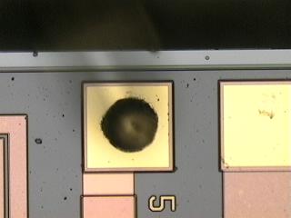
Wire bond ball with an "all black" appearance
|
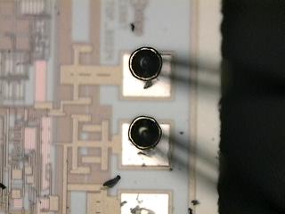
Wire bond balls with a "golden ring"
|
Added
in version 6.69 (dated December 4th 2001)
:
-
We've added support in
VisionGauge� for the QImaging
RETIGA FireWire™ (IEEE-1394) digital cameras. The
complete list
of video acquisition devices supported by VisionGauge�
is available in the "Frequently Asked Questions" (FAQ#1.2) section.
Added in version 6.68
(dated November 20th 2001)
:
-
We've added support for "*.avi"
movie files in VisionGauge's�
Video Sequence Capture Tool. VisionGauge� can now save the video to
disk either as a sequence of individual bitmap images or as an "*.avi"
movie file that can be played by other applications such as RealPlayer
™ and Windows Media™ Player. In all cases,
the video
is captured and saved at full resolution and without compression, in
full
color and at full video frame-rate. VisionGauge's� powerful Video
Sequence
Capture tool allows you to capture full frame-rate video (or slower, if
specified by the user) to system memory. Once captured to memory, the
video
can be played back, modified, saved to disk & retrieved later
on, etc...
The amount of video that can be captured (i.e. duration) is only
limited
by system memory.
- We've added support for
Integral Technology's FlashBus MV
family of video acquisition boards in VisionGauge's� Video Sequence
Capture tool.
-
In VisionGauge's� Video Sequence
Capture tool We've added
user-selectable begin & end delays. These "delay" parameters
can be
useful as fine adjustments to solve any "sync" issues that might occur
in your system at the beginning & end of captured video
sequences.
Added in version 6.65
(dated November 9th 2001)
:
-
We've added support for "*.dxf"
CAD file "ARC" entities in
VisionGauge's� Live Image Overlay Builder. The list of supported
ENTITIES
is now as follows: LINE, CIRCLE, LWPOLYLINE and ARC.
-
In the Motorized Stage
Configuration of VisionGauge�,
We've added an "Options" sub-menu in the Motion Toolbox. This new
Options
sub-menu has a setting that allows you to tell VisionGauge� to save
the complete system configuration (i.e. a "setup" file) along with the
part programs. This is useful if you want to associate different system
settings, such as measurement units or motion control settings, for
example
with different parts.
-
The Online Help has been
expanded to include all of the information
contained in the latest revision of the VisionGauge� User's Guide.
The online help, with its search capabilities, is a very efficient way
for users to locate relevant information needed to solve their
application.
Added in version 6.61
(dated October 12th 2001)
:
-
In the stage-based
configurations of VisionGauge� (compatible
with both manual- and motorized-stages) We've added the ability to
display
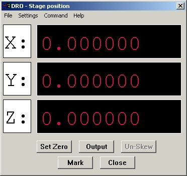
the Digital-Read-Out (i.e. DRO) in either regular or large format. The
new large format DRO has the appearance of the old "DRO boxes" with
which
many more experienced shop-floor operators are familiar.
Regular format DRO:
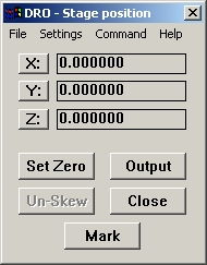
Large format DRO:
- We've added support for
the new "Intel(R) JPEG Library Version
1.51 for Windows", released October 10th 2001. This will ensure that
VisionGauge�
has the best and most up-to-date support for JPEG-format image
files.
Added in version 6.60
(dated October 5th 2001)
:
-
In the Motorized Stage
Configuration of VisionGauge�
We've added the capability to set the Hold & Run Currents (in
the "Advanced
Motion Control Settings") individually for each axis (instead of a
single
Hold Current value for all three axes and a single Run Current value
for
all three axes).
Added in version 6.58
(dated October 1st 2001)
:
-
We've added support for DXF
format CAD files in VisionGauge's�
Live Image Overlay Builder. When you read-in a DXF file into the Live
Image
Overlay Builder, VisionGauge� can automatically scale the drawing to
match-up with the system calibration. This means that if something
measures
one inch in the CAD drawing, it will appear the same size on the screen
as a one inch object under the camera. This is the perfect tool to
compare
a part against its CAD drawing: VisionGauge� scales the CAD drawing
appropriately and draws it "on top" of the part!
Other display options are also
available: you can
scale the CAD drawing to fit inside the image or you can specify your
own
scaling coefficient.
Autodesk developed the
DXF (Drawing eXchange Format) file
format for use in its CAD program AutoCAD. The DXF file format is very
general and it can contain many different types of data. At present,
VisionGauge�
supports the LINE, CIRCLE and LWPOLYLINE dxf ENTITIES.
Added in version 6.57
(dated September 11th 2001)
:
-
We've added a new "Measurement
Toolbox" to VisionGauge�. This new tool allows you to pre-define and
then store different measurement tools in the Toolbox's buttons. You
can
then quickly recall the measurement tools that you have defined simply
by pressing the appropriate button in this new Toolbox. This saves you
from having to re-open the "Settings | Measurement Mode" window and
selecting
the appropriate settings.
This new Measurement
Toolbox works very much like VisionGauge's� Calibration toolbox in
that:
-
its contents are carried
over from session to session
-
it can display either
10 or 20 measurement tools (i.e. buttons) at once
-
you can save the entire
contents of the measurement Toolbox to disk, and read-it in later on
This new Measurement
Toolbox is found in the "Tools" sub-menu. It can also be called-up
using
the "Ctrl-X" hotkey.
The procedure to define
and load a measurement tool into the Measurement Toolbox is simple:
-
Start by going into VisionGauge's�
"Settings | Measurement Mode" window (you can also use the "Ctrl-E"
hotkey
to do this) and set everything just the way you want it (i.e. select
the
appropriate measurement tool, of course, but also set the measurement
tolerances
- if any - the options, etc...). When you're satisfied with your
selections,
click "OK".
-
Then open-up the "Tools
| Measurement Toolbox" (you can also use the "Ctrl-X" hotkey to do
this).
-
Then - in the Measurement
Toolbox's menu - select "Set | Button #1" (if you want to load this
measurement
tool in The Toolbox's Button # 1). You will be asked to supply a label
for this measurement tool. You can of course use the name of the tool
itself
(for example: "point-to-point"). But you could also specify another
label,
for example: the name of the feature that you will measure using this
tool
(e.g. "Gasket thickness", "Line width", etc...)
-
Now, every time that you
press on the Measurement Toolbox's Button#1, this tool will
automatically
be loaded into VisionGauge�. Furthermore, an arrow indicator will be
displayed to indicate that this is the active measurement tool.
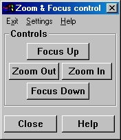
We've also added support
for Motorized Zoom & Focus in
VisionGauge(r).
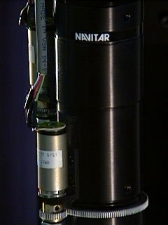
At this moment,
VisionGauge(r) supports motorized zoom
& focus using stepper motors. The "Motorized Zoom &
focus" interface
(shown below) is very intuitive and it allows also the user to set both
the zoom & focus velocities.
Added in version 6.56
(dated August 30th 2001)
:
-
We've added a new "Interlace
Offset Correction Tool" to VisionGauge�. This new tool is very useful
to correct "interlace offset error" that can occur in images captured
using
an interlaced video signal. The most common manifestation of such
"interlace
offset" error is "motion blur" between odd and even numbered lines in
the
image. Here is a "before and after" example that shows how this tool
can
be used to easily correct for interlace offset error:
|
Before

|
After
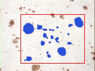
 |
-
In VisionGauge's�
"Counting and Sizing" tool, it is now possible to define a "Region Of
Interest".
You can use a Region Of Interest to limit the Counting and Sizing
tool's
scope to a user-selected portion of the image, rather than the entire
image.
This new "Region Of Interest" feature is fully integrated with all of
the
other powerful tools that are already part of VisionGauge's extensive
image
analysis toolset.
Added in version 6.54
(dated August 6th 2001)
:
-
We've added support in
VisionGauge� for the Integral Technologies Inc
FlashPoint
3Dx� family of video
acquisition and display boards.
The 3Dx� is a direct
replacement for the 3D�
family of video acquisition & display boards.
-
We've added support in
VisionGauge�
for the EPIX PIXCI�
SV5 video acquisition board. The SV5 is a direct replacement for the
SV4
of video acquisition board.
-
The complete list of video
acquisition devices supported
by VisionGauge�
is available in the "Frequently Asked Questions" (FAQ#1.2) section.
- We've added two new
"Horizontal Profile" and "Vertical Profile"
tools in VisionGauge�.
Both of these can be accessed through VisionGauge's�
"Tools" sub-menu. You can use these tools to plot either a horizontal
or
vertical profile across the image of one of the following channels:
either
luminance, intensity, hue, saturation, red, green or blue. The user can
select the profile position, either by dragging the hash mark in the
image
itself or by entering it manually.
Added in version 6.53
(dated July 23rd 2001)
:
-
We've added the ability
in VisionGauge� to load-in different "Report Configuration Files" at
runtime. This effectively adds "multiple report template" support and
"multiple
database" support to VisionGauge's� report Generator and Database.
-
We've added support for
multiple levels of "undo/redo" operations in VisionGauge�. This makes
it possible for users to "go back" many steps in their work (for
example:
if you want to change something that you did to the image 7, 10 or 15
operations
earlier...). You can set the number of "undo" levels through the
"Settings
| General Preferences" menu option. It is important to keep in mind
that
each extra "undo" level can take up quite a bit of memory, as every
"undo"
level requires that one full copy of the image be stored in memory.
This
consideration is especially important if you are working with very
large
images or if your computer doesn't have much RAM.
Added in version 6.52
(dated June 22nd 2001)
:
-
We've added support in
VisionGauge� for the Integral
Technologies Inc FlashBus MX� family of video acquisition
boards.
The FlashBus MX� is designed to
capture RGB and monochrome
video in real time from both standard and non-standard analog cameras.
It is capable of capturing both high resolution (up to 4K � 4K) and
high-speed video.
Another noteworthy
feature of the FlashBus MX� is
that, with an RGB video signal, it digitizes all three channels with a
resolution of 10 bits (as opposed to the more standard 8 bit
resolution).
This results in very high-quality imagery.
Please note that
VisionGauge� has true native support
for the FlashBus MX� and that it supports both the board's "On Screen"
and "Off Screen" video capture modes.
The complete list of
video acquisition devices supported
by VisionGauge� is available in the "Frequently Asked Questions"
(FAQ#1.2)
section.
Follow this link to
see the previous list of enhancements
(i.e. those
that are slightly less recent)
|


