VisionGauge�
Latest Improvements
VISIONx
INC. is always working
to improve VisionGauge�. The main improvements
and new features
that have been added to VisionGauge� (version
6.51) since
the previous major release (i.e. version 5.45) are the following:
-
Improved TIFF
image file format support.
-
It's now
possible to select multiple
images at once in the "Perfect focus" tool's window.
-
Improved
"Full Screen Live Video" support.
-
VisionGauge's�
"Counting
& Sizing" tool can now be told to ignore objects that touch the
image's
borders (we have included individual controls for the top, bottom, left
and right borders of the image).
-
Also in
VisionGauge's�
"Counting & Sizing" tool, we've added controls that allow the
user
to select the colors used to draw the objects (i.e. the color used to
draw
all of the objects in the sample as well the color used to draw
individually
selected objects).
-
In both the
Manual- and Motorized-Stage
Configuration of VisionGauge�, we've added
support for serial-port
devices, such as micrometer heads, height gauges, dial indicators,
etc...
VisionGauge� can now read in the stage position
for any
and all of the 3 axis through such serial-port data sources.
-
Users can now
set the file name as well
as the image file format (either Bitmap, JPEG, TIFF, or Targa) for the
one-key (or one-click) "Image Quick Save" tool. This is done through
the
"Settings | General preferences" menu command. These new settings are
also
saved in the "Setup" files.
-
We've added
some last enhancements that
have to do with stage control & automated measurements. With
this release,
the "fully-automated stage-based measurements" feature is now complete
& fully tested.
-
We've added
an "Options" menu to the
Calibration Toolbox that will allow you to increase the number of
pre-saved
calibrations up to 20.
-
We've added
the ability to rotate images
by an arbitrary (i.e. user-set) angle.
-
In the
motorized stage configuration
of VisionGauge�, we've corrected the software's
control
of very, very fine movements. These improvements have eliminated small
"jumps" and very fine "backlash" motions that could occur at very low
speeds
and that were only visible at extreme magnifications.
-
We've added a
new "Video Sequence Capture"
tool to VisionGauge�. You can use this new
feature to capture
full frame-rate (or slower, as set by the user) video to system memory.
Once captured to memory, the video can be played back, modified, saved
to
disk & retrieved later on, etc...
The
amount of video that can be captured
(i.e. duration) is only limited by system memory. Furthermore, with the
appropriate video acquisition hardware, VisionGauge�'s
new
"Video Sequence Capture" tool supports both analog and digital
cameras.
This
new feature is especially useful
for time-dependent processes (e.g. motion tracking, etc...)
-
It's now
possible for the user to manually
set the COM port initialization string when using serial port data
sources
for stage position feedback.
-
We've
improved VisionGauge's�
support for the PIXCI SV4 video acquisition board (for analog cameras):
higher live image refresh rate & better control of colors.
-
We've
improved VisionGauge's�
support for the PIXCI D video acquisition board (for digital cameras)
and
have added support for cameras that have a higher live image refresh
rate.
-
We've added a
new "Automated Angle"
measurement tool to VisionGauge�. With this
tool, the user
draws two "boxes" on the image and VisionGauge�
then finds
the strongest edge in each of these boxes and return the angle between
these two edges.
-
With the
"Marker-to-marker" measurement
tool, the "Center of circle" marker now uses the same number of
measurement
points as the "diameter" and "radius" measurement tools (i.e. more than
3, allowing the user to define a "best fit" circle).
-
We've added a
new "Zero position" marker
to VisionGauge's� "Marker-to-marker" measurement
tool. This
"Zero position" marker is used for stage-based measurements and allows
you to measure the distance between any other type of marker (e.g.
"Center
of circle", "Center of arbitrary 4-vertex feature", etc...) and the
stage's
zero position. VisionGauge's� new "Zero
Position" marker
is especially useful when you need to measure the distance between one
(common) reference position many different features. In this case, if
you
set the stage "zero" to the common reference position you'll be able to
carry out all of your measurements very quickly because you won't have
to re-define the reference position for every measurement.
-
We've added a
new "Orthogonal to line"
marker to VisionGauge's� "Marker-to-marker"
measurement
tool. This "Orthogonal to line" marker allows you to measure the
orthogonal
(i.e. shortest) distance between any other type of marker (e.g. "Center
of circle", "Center of arbitrary 4-vertex feature", etc...) and a
line.
-
In the
Motorized Stage Configuration
of VisionGauge�, we've linked the jog velocities
& accelerations
to the system's optical magnification. The jog velocities and
accelerations
for the three jog modes (i.e. slow, medium and fast) are those used
when
the operator moves the stage with either the external or on-screen
joystick.
Here's how this works: VisionGauge� now saves
the jog velocities
and accelerations to the calibration toolbox, along with the
calibration
coefficients. This way, when the user presses one of the buttons in the
Calibration Toolbox, the corresponding jog velocities and accelerations
are loaded into VisionGauge�, along with the
corresponding
calibration coefficients. This is very useful, as it is often desirable
to vary the jog velocities and accelerations depending on the optical
magnification
(i.e. we generally want slower movements at higher magnifications, and
faster movements at lower magnifications).
-
In
VisionGauge's� Area
Measurement tool, in addition to the existing "Straight line" drawing
capabilities,
we've added "Free hand" drawing capabilities.
-
We've added
"Measurement Tolerances"
to VisionGauge�. You can enable this feature and
set the
upper and lower measurement limits through the "Settings | Measurement
mode" menu option. "Measurement Tolerances" are especially useful when
carrying out fully automated stage-based measurements using the
Motorized
Stage Configuration of VisionGauge�. In this
case, you can
tell VisionGauge� to terminate (or not) the
automated measurement
program upon encountering an out-of-tolerance measured value by
checking
the appropriate box in the "Settings | Motion Control" menu option of
VisionGauge's�
Motion Toolbox. Please note that, when carrying out fully automated
stage-based
measurements with VisionGauge�, it is possible
to set different
upper and lower limits for each individual measurement, in exactly the
same way that it possible to set different modes for each individual
measurement.
It is also possible to turn the "Measurement Tolerances" feature On or
Off for each individual measurement. So, for example, it is simple to
create
an automated measurement program comprised of three measurement: the
first
a simple "point to point" measurement that should not be compared
against
any limits, the second a "marker to marker" measurement that must be
within
certain limits, and the third still another type of measurement that
must
be within a different set of lower and upper limits...
-
VisionGauge�
now supports
a new PCI bus quad card. In the Manual- and Motorized-Stage
Configurations
of VisionGauge�, a quad card is used to
accurately read-in
the stage's position. The existing ISA bus quad cards will continue to
be available. However, because PC manufacturers are gradually
eliminating
ISA slots from their computers, compatibility with this new PCI bus
quad
card will allow VisionGauge� to remain current
with the
evolution of the PC architecture.
-
We've enhanced VisionGauge's�
JPEG image file support, by updating to the new release of the Intel
JPEG
Library (i.e. version 1.5, released on Friday October 27th 2000).
-
We've improved the auto-focus
(added
an "emergency stop", etc...) and we've also carried out some minor
improvements
having to do with stage motion control.
-
We've further enhanced our
support of
JPEG image files.
-
We've added the ability to
"Zoom out"
when working with very large images (i.e. larger than the available
viewing
area. This allows you to "see" - and work on - the entire image all at
once, without having to actually reduce it's resolution. When you press
"Zoom out" a second time, the image is once again displayed in full
resolution
(with the usual "slider bars" for scrolling...).
-
We've added support in
VisionGauge�
for EPIX's� modified drivers for their PIXCI D�
& PIXCI SV4� video acquisition boards.
-
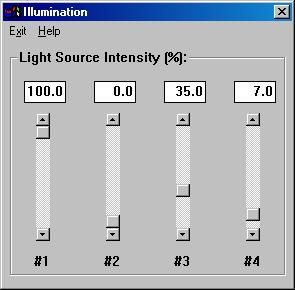
VisionGauge�
now supports
"Computer-Controlled Illumination". This means that VisionGauge�
will now let you control up to 4 different light sources.
The "Computer-Controlled
Illumination"
menu command is located in VisionGauge's�
"Command" sub-menu.
You can also use the "Control-U" hotkey combination to activate it. The
interface through which you control the light sources is very
intuitive.
You can either use the slider-bars to raise & lower the light
intensity
coming from each source or you can directly type in the relative
intensity
that you want.
Furthermore, the intensity of
each
source is saved in the "setup" files, so that when you recall a "setup"
from disk, the intensity of all of the light sources is automatically
re-set
to the appropriate values saved to disk.
VisionGauge's�
new
"Computer-Controlled Illumination" feature is very useful to speedup
operations
(i.e. much faster than having to reach for light source knobs) and also
leads to much more repeatable light intensities, which results in more
repeatable & accurate measurements.
- We've
added the "File | Open..." and "File
| Save As..." menu commands to VisionGauge's�
Calibration
Toolbox. You can use these new commands to save to disk the entire
contents
of the Calibration Toolbox & reload it later on. This is
especially
useful if different users of VisionGauge� want
to setup
the Calibration Toolbox differently. It is also another way to have
rapid
access to more calibrations than the toolbox's current maximum of 20
pre-saved
values...
-
We've added four "image
stitching" tools
(i.e. "left", "right", "above" and "below") for creating mosaics by
putting
images side-by-side. You can find these new tools in VisionGauge's�
"Edit" sub-menu.
-
We've enhanced VisionGauge's�
"Computer-Controlled Illumination" feature: when you change the
illumination,
Live Video is turned On automatically, so that you may directly see the
results on-screen.
-
We've added a new "Combine"
feature
to VisionGauge's� "Video Sequence Capture" tool.
You can
use this new "Combine" feature to transform the video sequence - made
up
of many component images - into one (large) image. The "Combine"
feature
also allows you to a) specify an image offset (to get rid of any
overlap
that may exist between side-by-side images) and b) resize the resulting
"combined" image.
You'll find this new "Combine:"
feature
especially useful when you're capturing video of a moving object or
scene.
In this case, the "Combine" feature allows you transform the video
sequence's
many component images into one (large) image of the entire object (or -
in the case of a moving scene - the "Combine" feature lets you build a
single "panorama" image from the video sequence).
- We've
improved VisionGauge's�
support of very(!) large images (i.e. enhanced memory management and
image
display routines as well as improved image manipulation tools).
-
We've enhanced VisionGauge's�
to allow field-of-view measurements during "Live Video" acquisition. To
enable this feature, check the "Allow Measurements during Live Video"
checkbox
in VisionGauge's� "Settings | General
Preferences" menu
option. Please note that - like all of the other settings and state
variables
- this checkbox's state is saved in VisionGauge's�
"Settings"
files. It is important to note, however, that edge-detection is not
available
for such "Live Video" field-of-view measurements (e.g. edge-detection
is
not desirable because of vibration, etc...).
-
We've added new "freehand"
drawing tools
in both the "Live Image Overlay Builder" and the "Annotation Toolbox".
To add a "freehand" overlay or annotation, simply select this new tool
from the appropriate menu, click once on the image to activate the
"freehand
drawing" tool, move the mouse to draw in "freehand" mode and click on
the
image a second time to turn the "freehand drawing" tool off. This new
tool
is very useful for outlining unusual shapes or boundaries, for example.
-
We've added a new "Pathline"
measurement
tool in VisionGauge�. This new "Pathline"
measurement tool
can be used both for field-of-view measurements as well as for
stage-based
measurements beyond the optical field-of-view (and this with both
manual
and motorized stages). A typical example of an application for this
tool
is to obtain a precise measurement of the perimeter of an
irregular-shaped
object. Finally, it should be noted that this new "Pathline"
measurement
tool is fully compatible with VisionGauge's�
powerful edge-tracker
(for automatic edge-detection).
-
We've added Full-Screen Live
Video support
to VisionGauge� when using the Integral
Technologies FlashBus
MV family of video acquisition boards.
-
We've added multi-camera
support to
VisionGauge� when using the Integral
Technologies FlashBus
MV family of video acquisition boards.
-
With certain video display
boards, 640
x 480 images would be slightly "taller" than VisionGauge's�
display area when using a 800 x 600 "desktop" display resolution and
would
thus not be displayed entirely (i.e. a vertical slider bar would be
available
to scroll the image either up or down). We have resized the status box,
at the bottom of the main VisionGauge� window,
so as to
allow the entire image to fit "all at once" under these conditions.
-
In the Motorized-Stage
Configuration
of VisionGauge�, we've added the ability to
read-in "generic"
ASCII data files containing raw coordinate data. This data can then be
used to create full motion programs in VisionGauge�.
CAD
programs, as well programmable production machines (for example: CNC
drills
& routers, etc...) are able to output such raw ASCII coordinate
data,
making this a very generic and robust way to import existing part data
into VisionGauge�. Finally, please note that
this raw coordinate
data must be expressed in the same units as VisionGauge�
current measurement units (i.e. if VisionGauge's�
current
measurement units are microns, then this data must also be in microns,
etc...).
-
We've added the ability to add
"comments"
within a Motion Program. These are user-defined text messages that are
displayed at certain user-specified positions within the motion
program.
For example, you might want the message "Turn back-light on" or "Make
sure
that there is no remaining solder mask" displayed when the program
reaches
point #25...
-
We've added a "skew function"
in both
stage-based configurations of VisionGauge� (i.e.
the Manual-Stage
Configuration and the Motorized-Stage Configuration of VisionGauge�).
This feature allows you to adjust - or "correct" - both motion programs
& measurements for a part's skew. Another way to say this is
that VisionGauge's�
"skew function" allows you to create true XY programs & get
true XY
measurements even if the part is not perfectly "square" with the stage.
The skew function automatically "rotates the part" in memory so as to
make
it mathematically "square" with the stage.
It is very easy to create a
"skew
corrected" program using VisionGauge's� "teach"
mode. Simply
proceed as follows:
1. Start by setting the part's
"zero"
position;
2. Then, tell
VisionGauge�
how the part is skewed relative to the stage. You do this through the
"Command
| Skew Part..." menu command, either in the Motion Toolbox or the DRO
window.
VisionGauge� will then ask you to pick two
points along
the part's X-axis.
Then, when you
later recall this
part program and wish to measure a part that is skewed differently from
the first part, simply repeat the same 2 steps...
To disable skew-correction,
simply
press the "Un-Skew" button in either the Motion Toolbox or the DRO
window.
Please note that it is good
practice
to try to keep skew corrections as small as possible (i.e. you should
attempt
to keep parts as "square" with the stage as possible). If the parts are
skewed very differently from one to the next, then stage calibration
(either
LEC or NLEC) becomes critical.
-
We've added a new "Offset" tool
that
you can use to create & edit motion programs in the
Motorized-Stage
Configuration of VisionGauge�. This new "Offset"
feature
allows you to take the definition of a device (including all of the
related
motion program data) and make multiple copies of it at specific (X, Y,
Z) offsets.
As an example, let's consider a
sample with 4 rows of 5 devices so that, in total, there are 20
identical
devices. In this example, you would use VisionGauge's�
"teach"
mode to define a single device (including changes in illumination,
measurement
mode, etc...), and then make 5 copies of this device definition at
specified
(X, Y, Z) offsets, so as to obtain a complete row. In a second step,
you
would use the "Offset" tool to make 4 copies of this row, at the
appropriate
(X, Y, Z) offset.
It is now possible to change
the
"Live Image Overlay" line width in VisionGauge�.
This is
the width of lines used for both standard overlay objects such as
"Crosshair"
and "Bulls-eye" overlay objects, as well as the line width in
VisionGauge's�
"Overlay Builder".
-
We've added Non-Linear Error
Correction
(i.e. NLEC) in both stage-based configurations of VisionGauge�
(i.e. the Manual-Stage Configuration and the Motorized-Stage
Configuration
of VisionGauge�). NLEC allows you to correct for
system
inaccuracies that cannot be properly accounted for using simple linear
error correction (i.e. LEC).
To carry out NLEC, simply
select
the "Motion | NLEC..." menu command. You will then be asked to mark the
stage
zero position as well as the zero position of your calibration grid.
After
this, you will be asked to enter calibration points. Please note that
VisionGauge's�
NLEC requires - as a minimum - 10 calibration points. Also, VisionGauge�
has no special requirements as to where the calibration points are
located.
It is always a good idea, however, to attempt to space-out the
calibration
points somewhat uniformly. And it is certainly not a good idea to have
any area of the stage severely under-covered by calibration points.
Also,
if you see that your system has a noticeable and precisely located
point
inaccuracy, it is probably a good idea to increase the density of
calibration
points around this area.
Once you've completed NLEC,
VisionGauge�
will automatically save to disk all of the necessary calibration data
so
that it will always be applied until you either erase it from disk or
carry-out
a new NLEC calibration. The NLEC calibration data is saved in the file
named "VisionGauge.nlec". This file is located in the main VisionGauge�
sub-directory.
Once you've carried out NLEC,
it
is very important that you remember to set the stage zero position
every
time you startup VisionGauge�, before carrying
out any measurements.
You do this by giving the "Command | NLEC: Set Stage Zero" menu command
in either the Motion Toolbox or the DRO window.
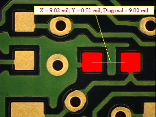
- We've
added a new type of "marker" to
VisionGauge's� "marker-to-marker" measurement tool: the
"centro�d
of a thresholded object" (sometimes, a thresholded object is also
referred-to
simply as a "blob"). This new type of marker is available for both
field-of-view
and stage-based measurements (either manual or fully-automated). In
both
cases, this is an extremely fast "one-point" measurement tool that is
very
simple to use: simply click on the object of interest and let
VisionGauge�
find it's centro�d.
So - for example - you can use
this
tool to measure the distance between the center of a "blob" and any
other
marker, such as the perpendicular distance to a line, or the center of
another blob, or a line midpoint or a simple point marker... Finally,
please
note that you can set different lower & upper thresholds for
markers
#1 and #2.
The following image shows a
simple example of a "marker-to-marker" measurement
where both markers are the "centro�d of a thresholded object" (the
thresholded object, in this case, is simply a PCB interconnect pad).
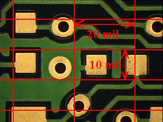
- We've added a new "grid" tool in both VisionGauge's�
"Live Image
Overlay
Builder" and Annotation Toolbox. When you access this new "grid" tool
through
VisionGauge's� "Live Image Overlay Builder", it allows you to put a
calibrated grid "over" the live video image, whereas when you access it
through VisionGauge's� Annotation Toolbox, it allows you to superimpose
a calibrated grid over a "frozen" image. The grid increment is
user-specified
and can be different along the horizontal & vertical axis (as
illustrated
in the image below). Finally, please note that the thickness, color
&
style of the grid's lines is entirely user-selectable.
- We've added three new measurement tools in
VisionGauge� to measure:
1. the area
2. the equivalent diameter, and
3. the radius
of a thresholded object
(sometimes, a thresholded object is also referred-to
simply as a "blob"). These new measurement tools are available for both
field-of-view and stage-based measurements (either manual or
fully-automated).
These are extremely fast "one-point" measurement tools that are very
simple
to use: simply click on the objet of interest and let VisionGauge�
carry out the measurement.
- We've
added the capability for programmable
illumination to the Motorized-Stage Configuration of VisionGauge�.
You should note that all of the editions of VisionGauge� have the
capability
for computer-controlled illumination, but fully-programmable
illumination
is only available in the Motorized-Stage Configuration of VisionGauge�
as it is only this edition that is capable of fully-automated
measurements.
This
fully-programmable illumination
feature lets you setup different illumination configurations at each
measurement
point. VisionGauge� can control up to 4 light sources. All of the
information
about the illumination configuration at each measurement point is also
saved in the motion program file, along with the rest of the coordinate
data & measurement mode settings so that the illumination
settings
are an integral component in the "part program".
It is also
worth noting that the
programmable illumination is extremely simple to setup. Another
noteworthy
feature is that VisionGauge� changes the illumination to the "next"
settings as soon as is possible (i.e. even before the stage starts
moving
to go to the next measurement point). This give the light sources as
much
time as possible to stabilize before VisionGauge� starts
carrying
out its measurements.
VisionGauge's� new programmable
illumination feature is another useful tool that will allow you to
solve
difficult applications and increase measurement repeatability!
- We've
enhanced VisionGauge's� automated
line width measurement tools tools to make them compatible withfully
automated
stage-based measurements. To do this, we've added the ability to
associate
a "Region of interest" (ROI) with each measurement point in a motion
program.
VisionGauge's� automated "Orthogonal line width" and "Arbitrary line
width" measurement tools can then be applied within this ROI.
-
We've added two new measurement
tools
to VisionGauge's� already extensive measurement toolset. These new
measurement tools will let you measure the maximum X & Y
dimensions
of a thresholded object (sometimes, a thresholded object is also
referred-to
simply as a "blob"). These new measurement tools are available for both
field-of-view and stage-based measurements (either manual or
fully-automated).
They are extremely fast "one-point" measurement tools that are very
simple
to use: simply click on the objet of interest and let VisionGauge�
carry out the measurement.
-
We've added a new "Centered
crosshair"
tool in both VisionGauge's� "Live Image Overlay Builder" and
"Annotation
Toolbox". When you access this new tool through VisionGauge's� "Live
Image Overlay Builder", it allows you to put a centered crosshair
"over"
the live video image, whereas when you access it through VisionGauge's�
"Annotation Toolbox", it allows you to superimpose a centered crosshair
over a "frozen" image.
-
We've added a "JPEG Image
Quality" setting
to the "Settings | General Preferences" window. Acceptable values for
this
setting range from 0 to 100. A higher value produces less compression
and
thus a better quality image, but of course a larger file size. Like all
other state variables in VisionGauge�, this parameter is saved in the
"setup" files.
-
We've added the ability to turn
the
Auto-focus & Edge Detection (i.e. VisionGauge's� "Snap Mode")
both
On & Off from within a Motion Program. The ability to do this
can come
in handy in some of the more challenging applications. These
enhancements
make our Fully-Automated 3D Measurement Systems even more
powerful
& just as easy to use!
-
We've enhanced VisionGauge's�
support
of the Integral Technologies FlashBus MV� video acquisition board.
For instance, we've added more on-line board-specific installation
instructions
that will help when setting up the board & with troubleshooting.
-
We've enhanced VisionGauge's�
Fully
Automated High Accuracy Volume Measurement Tool. Specifically, here's
what
has been done:
We've added more flexibility to
the
controls that allow you to define areas that you want VisionGauge�
to ignore for the volume calculations. You can also set &
change this
"disregarded" area's color in all of the different modes that are
available
to view the results (i.e. blended image, height map & 3D
projection).
We've also improved the
different
tools available for viewing the results and made them more
"interactive"
(e.g. the displayed "preview image" is changed as soon as you change
the
parameters).
We've also given the user more
control
over how the results are displayed (e.g. you can now change the mesh's
line width in the 3D projection mode, etc...)
Finally, we've also added some
extra
controls over the algorithms that actually do the volume computations.
We added a "limiter" control that you can use to tell VisionGauge�
to automatically disregard areas where the edges are very weak
(relative
to all of the other edges across the entire image). This new "limiting"
control can be very useful when you're working on a sample on which the
feature of interest is visible & clear, but where the
background is
very "flat" (i.e. there are absolutely no edges or visible features).
In
this type of a situation, the new limiting control is very useful to
tell
VisionGauge� that it shouldn't attempt to "find edges where there are
none".
- We've added a new "Calibrated Circle" tool in
VisionGauge's� "Live
Image Overlay Builder". This new tool allows you to precisely position
a circle of a user-specified diameter, at a user-specified (x, y)
distance
from the center of the field-of-view.
We've added a new "Calibrated Angle" tool in VisionGauge's�
"Live Image Overlay Builder". This new tool allows you to draw two
lines
that meet at the center of the field of view and that form a
user-specified
angle. You can also specify in which quadrant of the image this angle
is
to be drawn (i.e. Top-Left, Top-Right, Bottom-Left or
Bottom-Right).
Follow this link to see the previous
list of enhancements (i.e. those that are slightly less
recent)
|


