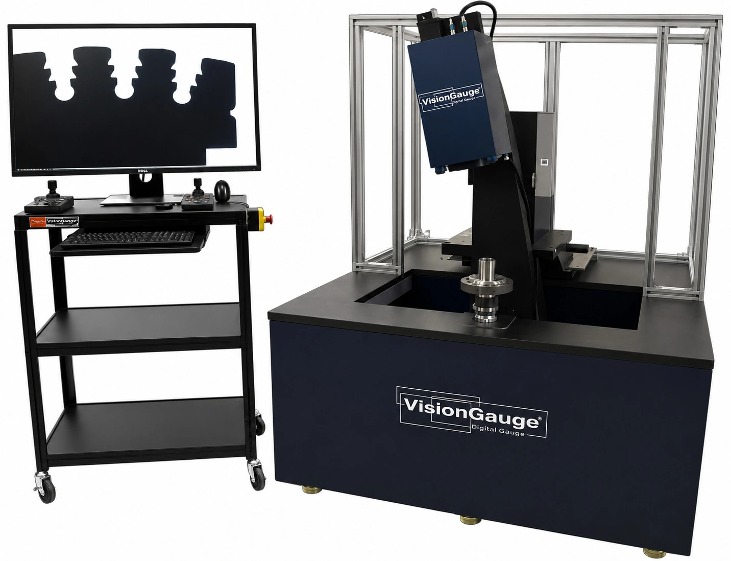
VisionGauge® Disk Inspection & Measurement Systems: Automated High-Accuracy Slot Inspection for Turbine Disks of All Sizes
Turbine disk slots are precisely shaped attachment points that lock every blade into a rotating disk, and they carry enormous centrifugal force at extreme temperatures. Blade roots, or the matching pieces that lock into those disk slots, reach a critical point of contact with the disk during operation. At this meeting point, the pressure surfaces are subject to very tight tolerances, generally 10–20 microns (µm).
The fit here must be very precise. A slot that is even slightly off in shape, position, angle, or spacing can cause uneven loading and shortened lifespan. The same goes for even a small dimensional error, surface defect, or crack, as these can interfere with blade fit or create a stress concentration.
Being able to accurately inspect 100% of the slots on a disk—rather than just a sample—is a real advantage for manufacturers.
Our VisionGauge® Disk Inspection & Measurement System is built specifically for this task. It delivers fully automated, high-accuracy turbine disk inspection with no operator-to-operator variation. It also works directly from your CAD data and inspects every slot on a disk, both large and small.
Quickly, easily, and accurately inspect 100% of a disk’s slots (both normal and at an angle).
5 axes of motion (X, Y, Z, Rotary, Tilt) to view slots at all angles and increment from slot to slot automatically.
Understanding Turbine Disk Slots: Fir Tree and Dovetail Profiles
Turbines, whether gas or steam, have a central rotating disk with blades attached around the rim. Where each blade attaches is called a root. It slides into a matching slot cut into the disk rim. The slot is effectively the mirror image of the blade root: the two have to fit together precisely so that load transfers evenly between them as the disk turns.
The two most widely used profiles for these slots and roots are the fir tree and the dovetail:
Fir tree: A tapered, multi-lobed, branching groove that spreads load across many contact points. It’s favored in high-load, high-temperature, high-stress sections of an engine.
Dovetail: Features a simpler, single-lobe profile that’s shaped similarly to a trapezoid. It’s ideal for lower loads and temperatures, typically found in cold compressors and fan sections of an engine.
In both cases, the disk slot has to match the corresponding fir tree turbine blade or dovetail root it will eventually receive. To ensure a proper fit, it is essential to accurately control the shape, position, orientation, and alignment of every slot on the disk.
What Makes Broached Slots Hard to Inspect
Turbine and compressor disk fir-tree slots and root forms are generally manufactured through broaching, wire cutting, or milling, along with follow-up deburring and rounding operations.
These profiles combine complex geometries with very tight tolerances that are difficult to achieve, and just as difficult to verify.
Several factors make broached slot inspection especially demanding:
Highly complex geometries with tight curves, internal radii, and other elements that are hard to measure accurately
Angled slots, including cone and helix angles, that cannot be viewed properly from a single fixed position
Large, heavy disks that are difficult to handle and position for inspection
High slot counts since 100% inspection means checking every slot around the entire disk, not a representative few
Broaching is commonly used to cut intricate fir-tree and dovetail slots that secure blades to turbine disks. Since these features are deeply recessed inside the part, conventional measurement tools often struggle to access them or capture their full geometry accurately.
Why Current Methods Fall Short
Many turbine disk manufacturers still rely on decades-old inspection technology. Traditional optical comparators use physical Mylar overlays and depend on an operator to judge whether a projected shadow matches a printed template.
This outdated approach is slow, prone to high rates of operator-dependent variation, and offers little automation or digital reporting. It also struggles with angled slots, large disks, and direct comparison to CAD data. For a feature as critical as a turbine disk slot, these limitations translate directly into risk and slower production timelines.
How VisionGauge® Automates Turbine Disk Slot Inspection
Our VisionGauge® Disk Inspection & Measurement System is designed specifically for turbine disk inspection and turbine slot inspection. Its patented software tools produce results of very high accuracy, completely automated, with no operator dependence or subjectivity. It is fast and can perform a complete inspection of 100% of the slots on every disk.
Here’s a look at how our patented tools make that possible:
CAD Auto-Align™
With the tight tolerances and complex profiles of a broached slot, even a small misalignment can lead to incorrect measurements. VisionGauge® patented the CAD Auto-Align™ tool, which automatically lines up a CAD file to the slot along one or multiple datums, or performs an overall best fit. Because alignment is automatic rather than operator-driven, it removes a major source of variation and drastically reduces inspection time.
CAD Auto-Pass/Fail™
VisionGauge® patented the CAD Auto-Pass/Fail™ tool, which instantly computes each slot’s deviation from nominal, compares it against bi-directional tolerances in real time, and produces a high-accuracy, fully automated Pass/Fail result. The tool also supports variable tolerances across the profile, so you can apply tighter limits on the critical pressure faces and looser limits elsewhere. This feature matches the way the part is actually engineered. In the system’s Auto-Pass/Fail™ Analysis mode, operators can snap directly onto failed edge points to quickly verify out-of-spec regions.
An Extensive Set of Measurement Tools
Beyond the two core tools, the system carries out a broad range of slot measurements, including:
Fully automated profile inspection
Completely automated knife-edge setup
Radial length / Z-plane distance inspection
Centerline inspection
Slot spacing and roll-pin distance measurement
Support for cone and helix angles
Verification of pressure-face flatness and slot perpendicularity
Want to see how it works on your part? Contact VISIONx, Inc. for a demonstration on your disk.
Many users combine VisionGauge® patented CAD Auto-Align™ and CAD Auto-Pass/Fail™ tools to fully automate their disk inspection. In practice, the process is straightforward:
The operator loads the disk in the mounting system and scans the barcode on the traveler.
The system loads and runs a part-specific program that automatically reads in the correct CAD file, auto-aligns it to each slot, and produces an Auto-Pass/Fail result.
Data for every inspected slot is automatically registered in its own Data Group, providing an organized digital record of the inspection results. Results can be reviewed instantly. Double-clicking a Data Group entry returns the system to that slot’s exact location, or single-clicking enables instant review of the image captured of that slot.
At the end of the inspection program, a complete inspection report is automatically generated, saved, and printed.
The result is fast, consistent, repeatable, and operator-independent turbine disk inspection, with complete digital traceability and no operator subjectivity.
Insights About The VisionGauge® Disk Inspection & Measurement System
Category
Capability
Automation
Fully automated operation, with no operator-to-operator variation
Inspects 100% of a disk’s slots quickly, easily, and accurately
Simple barcode reader and joystick interface for the operator
Extensive set of VisionGauge® advanced high-accuracy inspection & measurement tools
Ease of Use
Easy to program, using your CAD data directly
Fast, accurate, and easy to use
Intuitive software with patented, innovative tools
Operator-review mode to quickly revisit any out-of-tolerance areas
Motion & Operation
5 axes of motion (X, Y, Z, rotary, tilt) to view slots at every angle and move from slot to slot
High-precision movement on all axes
Standard travels of 12″ (X axis), 12″/24″ (Y axis), and 12″ (Z axis), with extended travels for larger disks
Tilt range of −40° to +40° and full 360° rotation
High load capacity for large, heavy disks
Robust, shop-floor-ready design
Imaging
Sharp, ultra-high-resolution imaging that captures fine detail clearly
Extended optical depth of field and working distance for added flexibility
High-resolution precision optics
Ultra-bright, computer-controlled LED lighting from both front and back
Data & Reporting
Automatic reports capturing measurements, statistics, and images
Built-in SPC and easy data export for complete documentation
Turbine disks operate in high-stress, high-temperature rotating machinery where safety and precision are non-negotiable. Accurate, repeatable turbine disk inspection is therefore critical across two primary sectors:
In aerospace and aircraft engines, disk slots must hold blades securely under extreme centrifugal load and temperature. Engine manufacturers and their suppliers face strict compliance requirements and depend on precise slot inspection to maintain safety and performance.
In power generation and energy systems, both gas and steam turbines use fir-tree and dovetail slot forms, and these components must meet established industry standards to run efficiently and safely.
Why Choose VisionGauge® for Turbine Disk Slot Inspection?
The VisionGauge® Disk Inspection & Measurement System transforms how you approach turbine disk slot inspection:
High Accuracy and Consistency
Eliminate operator-dependent variation and produce repeatable results, regardless of who runs the system.
100% Slot Coverage
Inspect every slot on every disk, including angled slots, quickly and automatically.
CAD Direct Comparison
Compare slots against your existing CAD data with no physical Mylars or manual overlays.
Higher Throughput
Accurately inspect and measure turbine disk slots faster, freeing your team for other critical work.
Complete Digital Documentation
Automatically generate reports and capture measurements, statistics, images, and Pass/Fail results for full traceability.
VisionGauge® software is field-proven across the company’s product lines, with more than 3,500 licenses in use worldwide. Every system includes a full one-year warranty along with a year of support and free software updates.
Modernize Your Turbine Disk Inspection With VisionGauge®
The VisionGauge® Disk Inspection & Measurement System is a comprehensive solution for automated, high-accuracy inspection of slots in turbine disks, both large and small. Our experts can help you configure a system that meets your application needs, including extended travels, custom workholding, and tooling for your specific disks.
If you are ready to modernize your turbine disk inspection, reach out today to get started!
The optical system delivers accuracy better than ±0.00015″ (4 µm), with linear encoder resolution of 0.25 µm and rotary encoder resolution of 0.005°. This precision helps manufacturers meet the strict tolerances required for turbine disk slot inspection in aerospace and power generation.
Yes. With 5 axes of motion, including tilt (−40° to +40°) and rotary (0° to 360°), the system can properly view and inspect slots at all angles, and it supports cone and helix angles.
Yes. The system offers high load capacity for large and heavy disks, extended travels beyond the standard 12″/24″ ranges, and a robust shop-floor design.
The VisionGauge® patented CAD Auto-Align™ and CAD Auto-Pass/Fail™ tools align the CAD file and produce Pass/Fail results automatically. This removes subjectivity and human judgment from the inspection process, so results are consistent and repeatable.
It uses the patented CAD Auto-Pass/Fail™ tool. The system:
Compares each slot to your CAD file
Measures how far it deviates from the ideal shape
Checks those deviations against your tolerances (tighter on the critical pressure faces, looser elsewhere).
The result is an automatic pass or fail with no operator guesswork. If a slot fails, review mode takes you straight to the spot that’s out of tolerance.
It checks the full slot profile against CAD and flags differences in shape, size, position, spacing, and angle. That includes slot spacing, centerline, radial length, roll-pin distances, cone and helix angles, and pressure-face flatness.
Inspection time depends on the turbine disk size, number of slots, and inspection requirements. However, with inspection times of just a few seconds per slot, the system can inspect a complete turbine disk quickly and efficiently, with minimal operator involvement.
The system automatically registers data for every inspected slot. It also creates reports and captures measurements, statistics, images, and Pass/Fail results. Built-in SPC and automatic export to Excel and other external applications support complete documentation and quality records.
No. The system inspects each slot optically, from its magnified image, so there’s no probe and no physical contact. Unlike a contact-based Coordinate Measuring Machine (CMM), it measures without touching the part, which means you get a faster, fully automated inspection and measurement solution.