
The optical comparator has been used in quality control in the manufacturing industry since it was first patented in 1925. The overall design hasn’t changed all that much, apart from some digital and software enhancements. The device’s continued popularity is a testament to its usefulness for visually inspecting parts for conformance and defects.
Below, we discuss what comparators are, and answer the following questions: what is an optical comparator used for, how to use an optical comparator, and how do traditional models compare to digital ones?
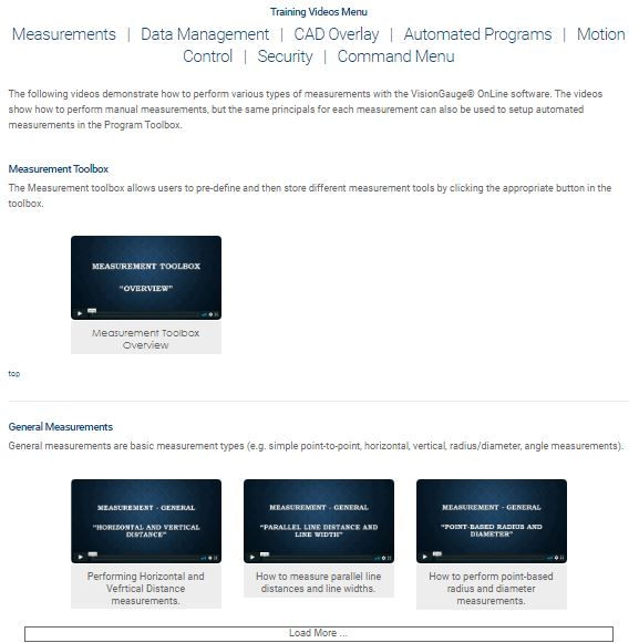
Learn how fast and accurate your inspection process can be.
What Is An Optical Comparator?
Optical comparators are measurement tools used in quality control to check for both dimensional accuracy and surface defects, such as scratches and indentations.
Also called comparators or profile projectors, they inspect, measure, and compare the dimensions of manufactured parts.
They enable non-contact measurement and observation, minimizing handling while still allowing close inspection.
How Does an Optical Comparator Work?
Optical comparators have changed little since their invention in the 1920s. The technology operates according to optical principles that have changed mainly in quality, not in function.
They work by using illumination, lenses, and mirrors to project a magnified silhouette of a part onto a screen. The image is then compared to the part’s prescribed limits.
Optical profile projectors are similar to overhead projectors used in classrooms. A light is directed through a stage to a series of lenses and mirrors, which then project the silhouette of whatever is on the stage onto a screen.
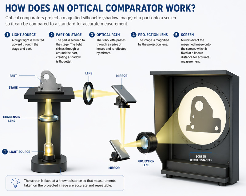
Optical comparators use this same principle. A part is affixed to a stage and a light source shines on it, resulting in a shadow image of the part. The shadow is magnified with lenses and bounced by mirrors onto the back of a screen. This screen is fixed at a known distance for measurement purposes.
Optical comparators can vary in size and magnification of the projected image. Both of these metrics depend on the optics and screen size of the comparator. Screen sizes for optical comparators range from 12 to 36 inches, though models with larger screens are available. However, larger screen sizes are only possible with larger enclosures, as a greater distance is required to generate a bigger image without distortion.
Primary Configurations of Optical Comparators
Optical comparators have two primary configurations: horizontal and vertical.
Horizontal Comparators
In a horizontal model, the optical comparator’s light travels horizontally, so the viewer sees a silhouette taken from the side of a part. This model works best for parts held in a fixed location, such as screws fastened in place or castings that must be held in a vise.
Vertical Comparators
In a vertical model, the optical comparator’s light travels vertically, so the viewer is looking down on the part. This works best for flat components that can lie on the work stage, such as gaskets. They also work well on flexible or soft elements that need to lie on a flat surface to provide an accurate measurement.
Optical comparators of both types can be found in manufacturing shops and lab environments. Their use is strongly related to quality control. They are most popular in industrial sectors, including the scientific, automotive, medical manufacturing, aerospace, and defense industries.
Measuring Processes of Optical Comparators
There are three different measuring processes for comparators:
- Silhouette measurement: The simplest measurement method is to project a silhouette of the image onto a screen for measuring. Because the magnification is known, the silhouette can be used to gain accurate measurements.
- Point comparison: The second measurement method is to compare the image’s silhouette to prescribed plan points on a screen. The part’s silhouette is centered on the screen, and the user moves the stage to hit various points on the screen. This measures how much the stage had to move to match the part to the point.
- Software analysis: The last measuring process is digital, using software to analyze and measure the image generated by the optical comparator.
The first two methods are used by traditional optical comparators and are the most common in the industry. The third is employed by digital optical comparators, which handle the entire process electronically.
Digital Optical Comparator vs. Traditional Optical Comparator
Optical comparators are available in both traditional and digital configurations. Manual comparators are straightforward and valuable in smaller applications.
However, they lack the efficiency and strength to keep up with large-scale production costs. These tools can only produce 2D renderings of simple parts one at a time, making them quite labor-intensive.
As a result, more operations are turning to advanced digital optical comparators for streamlined work and enhanced accuracy.
Understanding Limitations of Traditional Optical Comparators
Profile projectors are generally straightforward and require little training to use. Traditional optical comparators that use silhouette measurement or point comparison simply require the user to fix a part in place and observe the on-screen image.
Traditional optical comparators are easy to use and operate. However, they present significant disadvantages for users and clients precisely because of their simplicity.
Some primary flaws of traditional optical comparators include:
- Limited by complex geometries: Production parts are becoming more complex, and observing them from multiple angles is increasingly necessary. However, traditional comparators don’t accommodate this well.
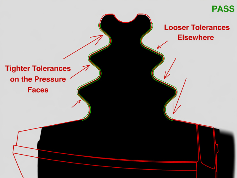
- Less accurate: Although traditional optical comparators can achieve very accurate measurements, today’s modern parts require tighter tolerances. This reduces the room for error allowed for any manual measurement method. Additionally, measurements can vary from operator to operator when inspected manually.
- Labor-intensive: Traditional optical comparators can only measure one part at a time. This poses a problem when inspecting large quantities of parts or multiple parts at once, which is often needed in the manufacturing industry.
- 2D limitations: Traditional optical comparators can only project 2D images onto a screen, which can make it difficult to analyze multiple dimensions simultaneously.
Although these limitations present no issues for non-repetitive tasks used to analyze 2D parts, anything outside of that is an obstacle for traditional optical comparators. For large-scale, complex analysis, a different model is necessary.
Our digital optical comparators are the modern upgrade your inspection process needs.
Digital Optical Comparators: The Modern Upgrade
Manufacturing companies need tools that are quick, easy to use, and can handle large quantities of complex parts. This is where our digital optical comparators come into play.
Digital optical comparators follow traditional optical comparators and apply new technology to key functions. The result is an automated system that is faster and easier to use, reducing operator error and input.
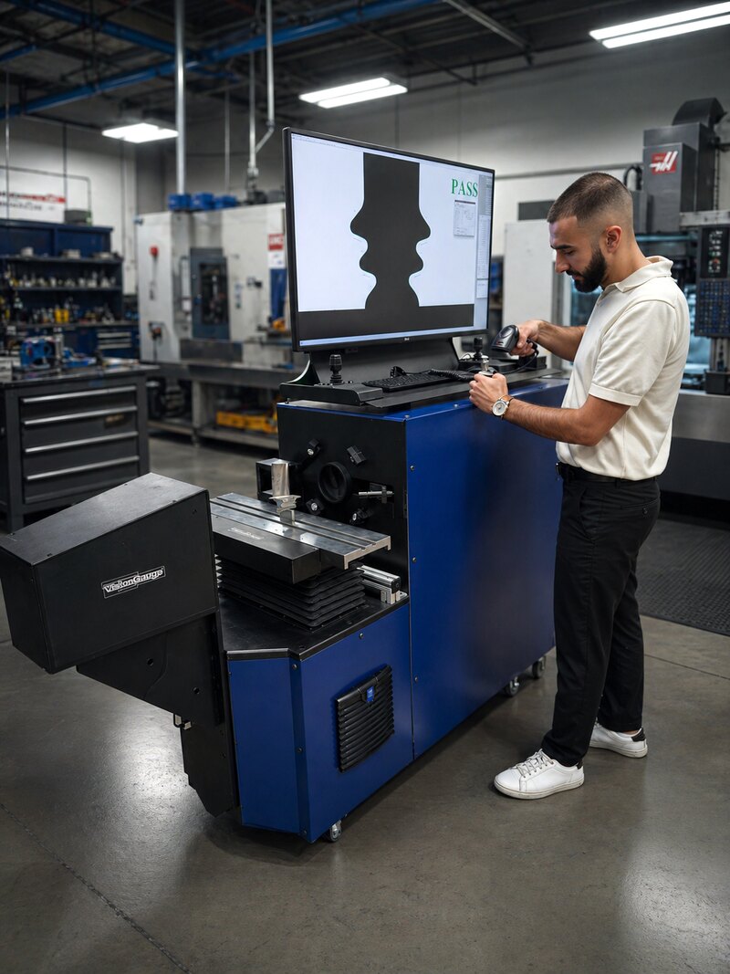
Digital optical comparators enable professionals to obtain precise, reliable measurements of their products, resulting in higher-quality production output. They use high-quality digital cameras, sophisticated software, and unique lighting techniques to analyze simple and complex parts, complete with practical 3D capabilities. They are extremely accurate yet easy to use, delivering fast, reliable results, completely operator-independent.
Where traditional optical profile projectors fall short, digital models pick up the slack. Manual comparator technology is highly useful for small-quantity applications, but as parts become more complex and large-scale manufacturing increases, automation is necessary. Our digital optical comparators present the solution.
Digital optical comparators offer the following advantages:
Automation
Our models use software and cameras instead of human eyes to analyze and measure parts. The software automates the measuring process and completes it more quickly than a human can.
Digital optical comparators are fully automated devices used with intuitive tools, such as the VisionGauge® patented CAD Auto-Pass/Fail™ and CAD Auto-Align™ featuressystems from VISIONx, Inc. These tools make the VisionGauge® Digital Optical Comparator completely operator-independent, increasing the dependability and repeatability of the results. Here’s more information regarding these tools:
- CAD Auto-Pass/Fail™: VisionGauge® Digital Optical Comparators deliver automatic reports, charts, statistics, and much more. This tool can determine whether a part is within tolerance, removing any operator subjectivity.
- CAD Auto-Align™: This tool creates the best fit for the CAD by automatically aligning it to the part along the datums. It travels along the length of small and large parts, even across multiple fields of view, to capture images at different locations and deliver information that matters.
Accuracy
Digital optical comparators are highly accurate devices that deliver precise measurement comparisons. Using advanced digital image processing and innovative computations, these systems can make corrections to enhance overall image quality. They can correct 2D non-linear distortion while performing other enhancements like sharpening edges and reducing noise to create a high-quality image.
While many traditional tools use templates and overlays, which tend to distort and stretch over time, these machines work with existing CAD plans for precise part comparisons. Digital optical comparator software also features sub-pixel edge detection technology to locate edges between pixels for ultra-precise results with minimal human error.
3D Capabilities
Digital optical comparators use multiple lighting techniques, additional positioning stages (e.g., rotary stages), and lasers to analyze parts in all dimensions, including 3D. This permits quick, one-shot measurements with minimal operator interference.
Quantity Management
The automated nature of digital optical comparators enables operators to analyze multiple parts without human intervention.
These advantages effectively maximize the accuracy of optical comparator measurements while reducing labor.
How to Use an Optical Comparator
When using an optical comparator with a traditional setup, the steps are simple:
- Placement: First, the operator must turn on the optical comparator and place the part to be observed on the staging area.
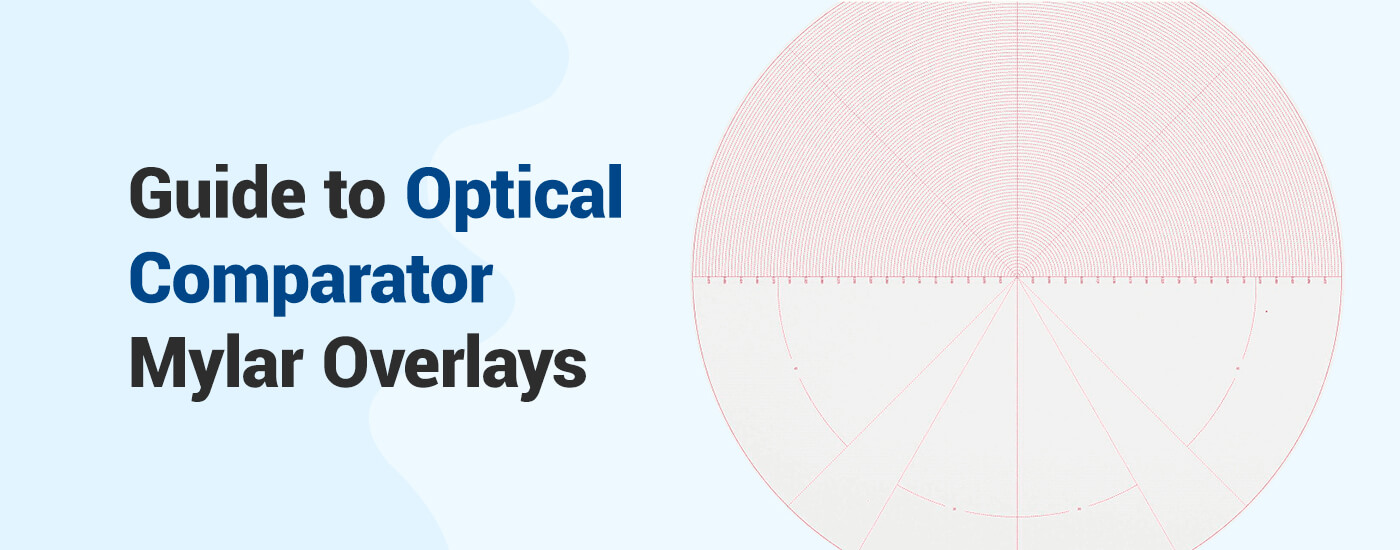
- Alignment: When the part’s image is projected on the comparator’s screen, the operator must place an overlay on the screen. The optical comparator overlay, also known as a template or Mylar, is a part drawing printed on a transparent overlay that is scaled to match the magnification of the comparator. The operator must manually align this overlay with the part’s image.
- Comparison: Once the overlay is placed, the operator compares the drawing to the image and identifies any discrepancies. From these discrepancies, the operator will determine if the part is within tolerance.
This is the process used for most traditional optical comparators, though there are various methods available for this technology. For example, instead of an overlay with a part plan, an overlay may feature a grid or concentric circles to allow for more precise measurements of a part.
Alternatively, a point comparison method may be used, where the image’s silhouette is centered on the screen compared to an overlay. The user then moves the stage to hit prescribed points on the overlay, measuring how much the stage had to move to match the part to each point.
Like traditional models, digital optical comparators use optics to compare a part to its plans. However, they do so by augmenting the existing comparator technology with a combination of measurement and analysis tools.
Digital optical comparators directly reference CAD drawings of your desired parts for comparison, along with laser measurement tools and advanced comparison software.
So what does this mean for operators?
Instructions for operators can be pared down to one simple step: place the part on the staging area.
From there, the digital optical comparator does the rest. The system will automatically handle alignment and comparison. Then provide a pass/fail result, along with analytical data supporting the decision.
Though designed for automation, the VisionGauge® Digital Optical Comparator system is also accurate and efficient when operated manually. An operator can perform direct measurements on a part or manually compare it to its CAD file.
The VisionGauge® software interface is also intuitive and easy to use for manual operation. Operators can quickly load part CAD files and pre-programmed inspection routines with the system’s barcode reader, and the stages and overlay can be manually controlled with the system’s industrial-grade joysticks.
Both automated and manual operation modes produce highly accurate results and complete documentation.
Applications of Digital Optical Comparators
Companies across a range of industries use digital optical comparators to solve various applications. Below are some common digital optical comparator uses and applications:
- Aerospace and Aeronautics: Aerospace manufacturers use optical comparators to inspect and measure turbine disks and slots, cooling holes, turbine blade fir tree roots, seal slots, and slots on five-axis parts. Digital optical comparators improve accuracy and repeatability, increase throughput, and collect electronic documentation – all essential functions in the aerospace industry.
 Automotive: In the automotive industry, digital optical comparators inspect flexible auto seals and trim and measure various components and parts. They are ideal for comparing seals against CAD data, especially when the components are difficult to inspect.
- Bearings: Precision bearings provide high runout accuracy and generally require support at high rotating speeds, often under large loads. They are used in a wide range of applications. A few examples include wind turbines, helicopter rotors, and gear drives. The VisionGauge® Digital Optical Comparator is used by manufacturers to check all types of precision bearings, directly on the shop floor. These systems are much faster and much more accurate than traditional approaches, and they eliminate operator subjectivity.
- Machining: Digital optical comparators include tools designed to check machining parts. For example, the patent-pending VisionGauge® Tooth Checker inspects screw teeth.
- Medical devices: Multiple tools are available for inspecting and measuring medical devices and implants with digital optical comparators. For example, the VisionGauge® Tooth Checker tool can examine implant screws. Optical comparators can also inspect stents, medical rasps, orthopedic implants, and more.
- Defense/military: Equipment used for military and defense purposes also benefits from inspection by a digital optical comparator. VisionGauge® can efficiently automate inspecting parts with large numbers of holes or other features and works much faster than other systems.
- Power and energy: Parts inspections are essential to your quality assurance processes, especially in the power and energy industry. These components work hard under extreme conditions, so they must meet established industry standards to operate efficiently and, more importantly, safely. VisionGauge® Digital Optical Comparators can aid quality assurance practices by inspecting industrial components with advanced, patented technology.
- Tool and dye: Digital optical comparators are ideal for use when you need to inspect thread rolling dies. You can set the system to automatically identify and check features based on your specifications.
These are just a few examples of how digital optical comparators can be used. Request a demo for your part!
Improve Efficiency and Quality with VisionGauge® Digital Optical Comparators
Using an optical comparator doesn’t require extensive training or massive labor inputs. Many manufacturers across a wide range of industries are using VisionGauge® systems to improve and speed up their inspection & measurement process, reduce their costs, improve product quality, and achieve much better Gage R&R performance.
Simplify your inspection with a variety of system types and configurations offered by VISONx, each suitable for any number of applications.
To learn more about our products, browse through our list of offerings or contact us online today.
Popular Posts