VisionGauge®’s CAD Auto-Align™ tool has now been enhanced to make it even more widely applicable. The tool can now be applied to very large parts that extend way beyond the system’s optical field-of-view. And in the same way, it can now be used on parts that have very large variations in depth and height, much larger than the system’s optical depth-of-field.
When dealing with large parts, the system scans the part (a single time) and captures and stores images of all of the areas of interest as well as the precise location at which each image is taken (using the system’s high-accuracy encoder readings). VisionGauge®’s proprietary algorithm then iteratively aligns the CAD to the part, across all of the images and along all of the prescribed datums. As these calculations quickly converge to the correct solution, the system does not need to revisit any of the image capture locations, thus tremendously speeding up the overall operation. All of the calculations throughout the entire process are carried out on the initial image buffers. This results in tremendous time savings and very fast overall performance, even when dealing with very large parts.
Furthermore, because there is no limit on the number of images used to encompass all of the part’s datums and features of interest, it is possible to carry out this CAD Auto-Align™ operation at high magnification, which produces very high accuracy results, even in the case of large parts.
5x hip implant inspection
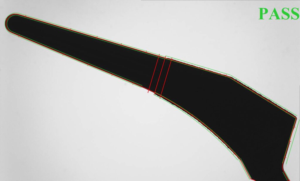
Image 2: 5X magnification – hip stem
Previously, the CAD Auto-Align™ tool operated on a single field-of-view. This means that for larger parts, a lower magnification needed to be used. This necessarily produced lower resolution and accuracy
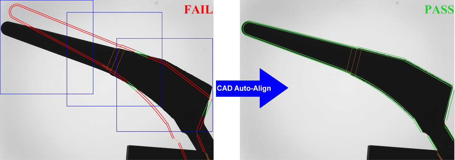
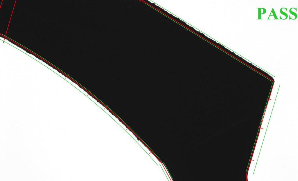
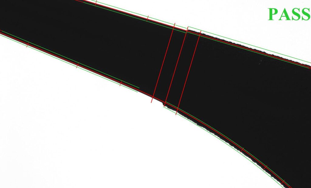
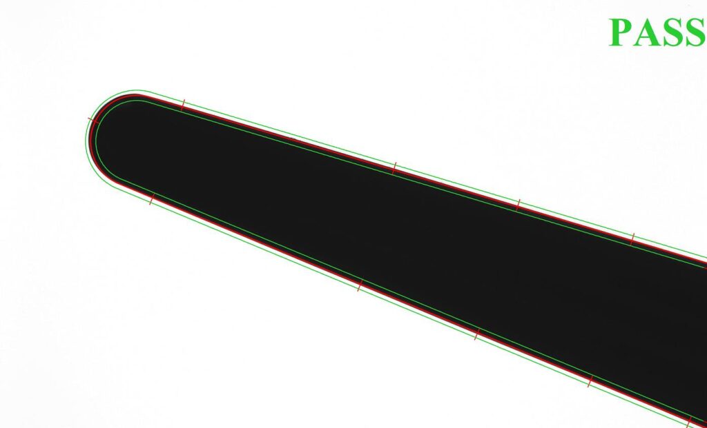
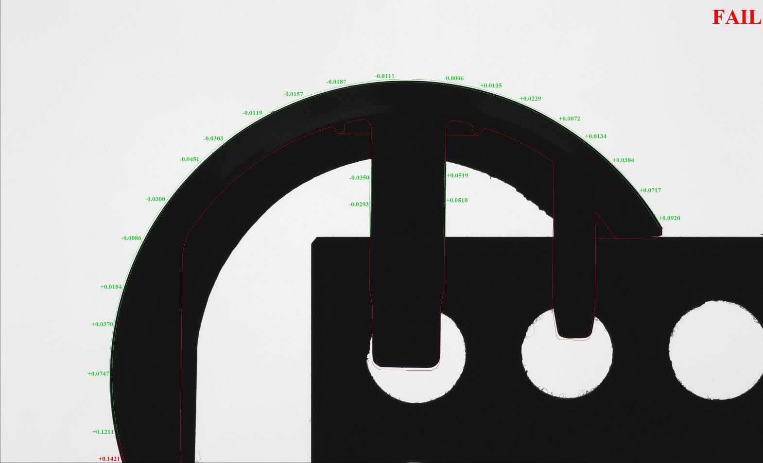
Image 3: 10X magnification – hip stem
Because the new enhanced CAD Auto-Align™ tool can now use multiple images to cover all of the part’s features of interest, it imposes absolutely no limitation on magnification and produces results of maximum resolution and accuracy.
For example: Images 2 and 3 above show the same hip stem. In Image 2, a lower (i.e. 5X) magnification is used so that the entire part fits within the field-of-view. In Image 3, a higher (i.e. 10X) magnification is used and the entire part is covered using 3 images. VisionGauge®’s new enhanced CAD Auto-Align™ tool carries out the CAD-to-part alignment across all 3 of these images and – because the system resolution is higher at 10X than at 5X – it produces a higher resolution and higher accuracy results.
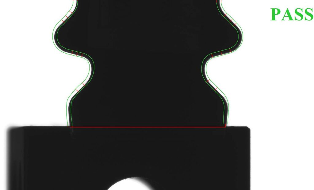
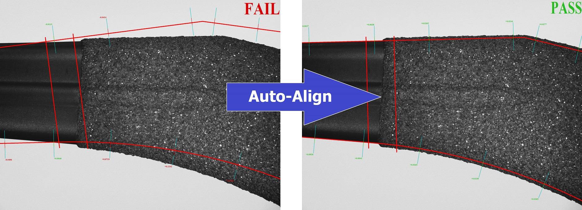
Image 4: Turbine blade fir tree at a lower (10X) magnification to fit the entire part inside a single field-of-view.
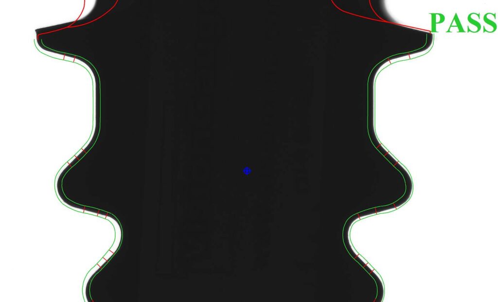
Image 5: The same turbine blade fir tree as above, but this time covered using 2 images taken at a higher (20X) magnification. VisionGauge®’s new enhanced CAD Auto-Align™ tool carries out the CAD-to-part alignment using both images. This approach produces an overall result of higher accuracy.
And in the same way that VisionGauge®’s enhanced CAD Auto-Align™ tool is able to deal with parts that are larger than the system’s (XY) field-of-view, it can also overcome depth-of-field limitations. Specifically: in applications where the variations of the part’s height or depth (i.e. along the Z axis) are greater that the system’s optical depth-of-field, images taken at different Z positions can be included in the image set. VisionGauge®’s new calculation algorithm is then able to carry out a CAD Auto-Align™ over the image entire set, taken at different Z (and also possibly X and/ or Y) positions and best-fit the CAD to the part in these situations as well.
All of these new enhancements are the subject of new patent applications.
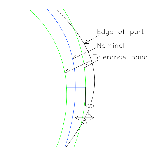
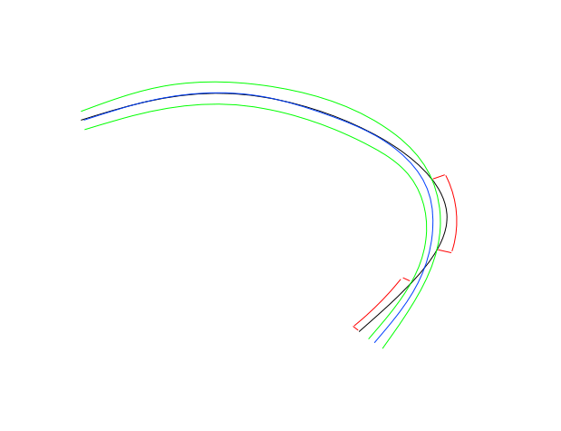
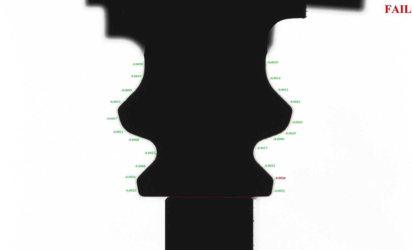
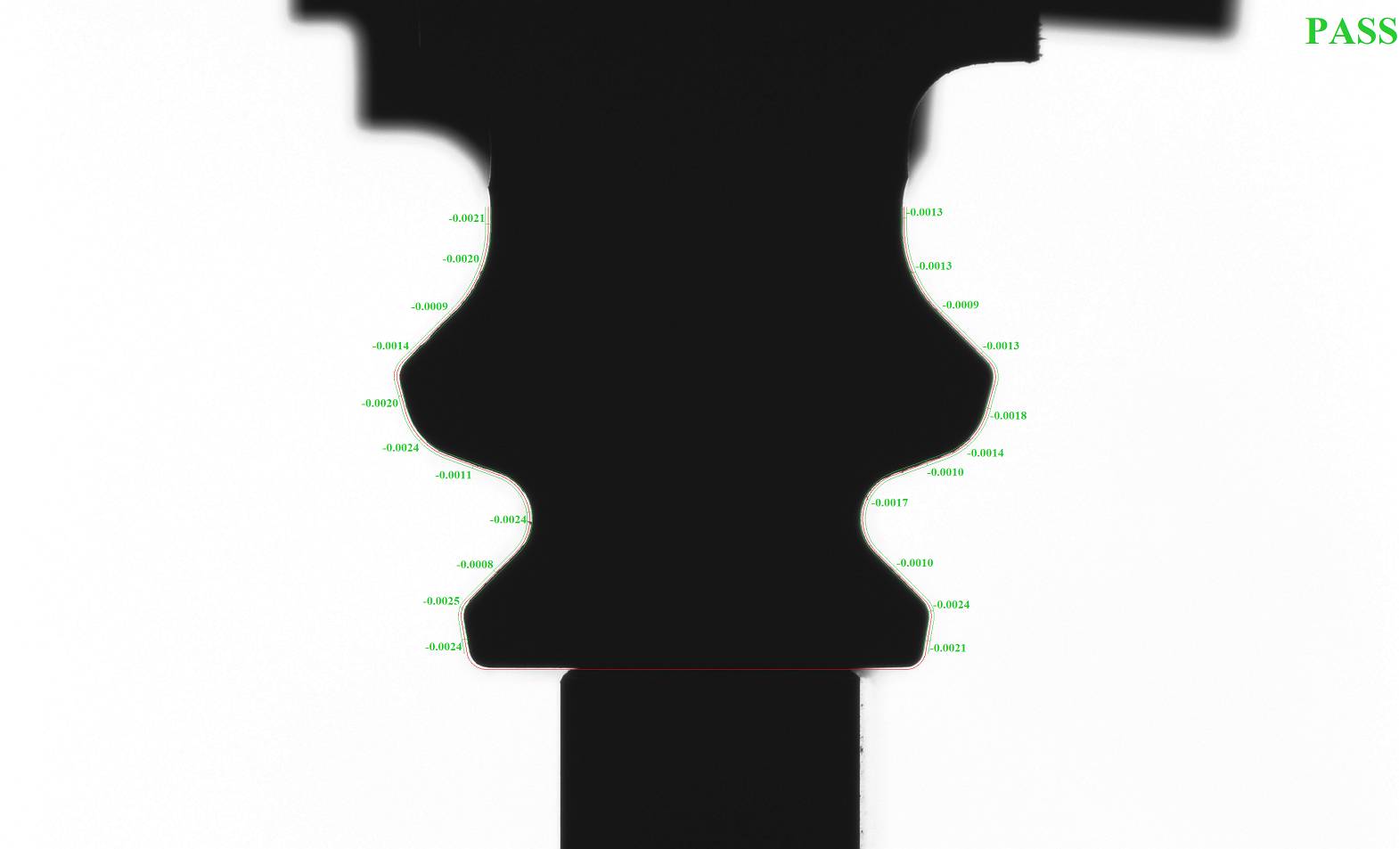
And, as previously, the results of VisionGauge®’s CAD Auto-Align™ operation can then be analyzed by VisionGauge®’s patented CAD Auto-Pass/Fail™ tool, all of which provide VisionGauge® with its unique and powerful ability for fully-automated high-accuracy part-to-CAD comparison.