Digital Optical Comparator vs. Traditional Optical Comparator
Optical comparators are innovative tools used throughout manufacturing applications to inspect, measure, and compare the specifications of various manufactured parts. These machines use high-quality lenses and mirrors to magnify a component’s silhouette onto a screen and allow for an in-depth examination, checking for defects and inaccuracies.
Optical comparators are available in both traditional and digital configurations. Manual comparators are straightforward and valuable in smaller applications but lack the efficiency and strength to keep up with large-scale production cost-effectively. These tools can only produce 2D renderings of simple parts one at a time, making them quite labor-intensive.
Instead, more operations are turning to advanced digital optical comparators for streamlined work and enhanced accuracy.
What Are the Benefits of Digital Optical Comparators?
Digital optical comparators allow professionals to obtain precise and dependable measurements of their products, resulting in higher-quality production output. They use high-quality digital cameras, sophisticated software, and unique lighting techniques to analyze simple and complex parts, complete with practical 3D capabilities.
Other benefits of digital optical comparators include:
Accuracy
Digital optical comparators are highly accurate devices delivering precise measurements and comparisons. Using advanced digital image processing and innovative computations, these systems can make corrections to enhance overall image quality. They can correct 2D non-linear distortion while performing other enhancements like sharpening edges and reducing noise to create a high-quality image.
While many traditional tools use templates and overlays, which tend to distort and stretch over time, these machines work with existing CAD plans for precise part comparisons. Digital optical comparator software also features sub-pixel edge detection technology to locate edges between pixels for ultra-precise results with minimal human error.
Usability
Digital tools streamline quality control and inspection procedures. They are quickly installed within various environments, allowing operators to incorporate them easily directly into their operations. Their small footprint optimizes floor space, and their mobility supports fast and efficient inspections throughout your location without needing re-calibrations in-between.
Digital versions use lenses with much larger depths of field, allowing the system to keep everything in focus while conducting inspections. This feature eliminates the need to refocus when continuously analyzing different sections of a specific part. Since this happens automatically, multiple parts can be examined without human participation, reducing labor costs while increasing throughput.
Due to their ease of use and convenience, these tools are widely used throughout numerous industries, such as:
Aerospace
Machining
Military
Power
Energy
Automotive
Telecommunications
Automation
Digital optical comparators are fully automated devices used with intuitive tools, such as the VisionGauge® patented CAD Auto-Pass/Fail™ and CAD Auto-Align™ systems from VISIONx, Inc. These tools make the VisionGauge® Digital Optical Comparator completely independent from operator to operator to increase the dependability and repeatability of the results. Here’s more information regarding these tools:
CAD Auto-Pass/Fail™: VisionGauge® Digital Optical Comparators deliver automatic reports, charts, statistics, and much more. This tool can determine whether a part is within tolerance, removing any operator subjectivity.
CAD Auto-Align™: This tool creates the best fit for the CAD by automatically aligning it to the part along the datums. It travels down the length of small and large parts, even across multiple fields-of-view, to collect imaging in different locations and provide information that matters.
Learn More About Digital Optical Comparators From VISIONx
VISIONx specializes in producing state-of-the-art automated imaging, visual inspection, and high-accuracy measurement solutions you can trust. We have created numerous digital optical comparator models capable of improving your site’s specific productivity and performance needs. With our patented VisionGauge® Digital Optical Comparator, you’ll ensure your products are within spec and avoid production flaws more easily than ever.
It’s no surprise that the global industrial automation market is expected to reach $430.9 billion by 2030. Automation is an increasingly popular engineering feat for more efficient labor, time and cost savings, increased safety protocols, and often better products overall. Discover the benefits of automation systems in various manufacturing industries.
What Is Automation in Manufacturing?
Manufacturing automation uses specialized equipment to streamline production assignments, systems, and processes. It’s incredibly helpful for repetitive tasks or those requiring high precision.
Manufacturing processes like assembling, inventory management, handling, processing, and quality inspection can all integrate automated technology. Automation in manufacturing aims to elevate capacity, lower operating costs, improve productivity, and enhance workplace safety measures.
Benefits of Automation Systems in Manufacturing
Below are some advantages automation can provide for manufacturing.
1. Increased Efficiency
Automated machines can work unattended 24/7, maintaining the same speed and efficiency throughout. Advanced equipment, robotics, and sensors can oversee inventory, system maintenance, and quality checks on completed products. They can seamlessly disperse this data throughout the supply chain. This maximizes scheduling and planning, decision-making, and return on investment (ROI).
Automation can help your operations persist longer and boost productivity. You can generate new or more products without disrupting manufacturing. Additionally, this increased production speed gives companies higher responsiveness to market fluctuations, helping them stay ahead of competitors.
2. Cost and Time Savings
Many machines can perform the work of several people at a time with fewer defects, offering significant value and cost savings in the long run. Automated technology can also generate more products and complete inspections in less time. This increased production rate saves considerable amounts of valuable time.
3. Higher Product Quality
Machines can typically complete manufacturing processes with greater accuracy than human employees, all while ensuring the same product quality throughout. This allows for a lower error rate and overall better products. Standards can be stricter and products more competitive in the market.
4. Improved Safety
In 2022, the Occupational Safety and Health Administration (OSHA) cited over 22,000 U.S. workplace safety violations among its leading complaints, including citations in fall protection, hazard communication, respiratory protection, and other areas.
Reducing human error with automation can create a safer workplace, as it reduces repairs, recalls, and potentially severe injuries. Before advanced machinery, many manufacturing processes required employees to work for extended periods around various hazards, such as chemicals, electricity, machine guarding, equipment maintenance, and more.
Generally speaking, incidents like machine malfunctions and slipping or tripping on loose materials can be prevented with this technology. Automation helps keep workers away from dangerous substances or processes.
5. Fewer Labor Shortages
Automated machines can combat labor shortages and their resulting effects, as they’re less likely to be in low supply than human workers. Sufficient labor makes all the difference in a manufacturing company’s success.
Top Industries to Benefit From Inspection Automation
Automation is revolutionizing many industries, from retail and transportation to electronics. Below are merely a few of many industries that benefit from automated processes.
1. Aerospace
Given the immense size and scale associated with aircraft, the aerospace industry faces complex manufacturing requirements. Large components often require human operators and robots to work in tandem. In many cases, mobile robots that can travel between large aircraft parts are necessary to facilitate the process.
Moreover, robots can work in tight, hard-to-reach spaces, further enhancing productivity and quality. Automation minimizes the need for aerospace engineers to perform repetitive tasks, manipulate heavy objects, squeeze into tight spaces, and perform other hazardous processes while still adhering to critical quality standards.
Airplanes components have numerous holes that require drilling. Using special vision technology, robots can accelerate this drilling process while improving accuracy. Additionally, robots can assist and perform a wide variety of other tasks in assembling, preparing, inspecting and testing aircraft parts and components.
2. Medical Manufacturing
Given automation can perform tasks with fewer errors and higher precision, it’s an excellent tool for manufacturing, reporting, and documentation of medical devices and pharmaceutical products.
Automated medical device and implant manufacturing enhances quality control, assurance, and consistency. Using complex computing technology, cameras, and sensors, it provides accurate inspections, error detections, and automatic corrections. It also outputs and stores results for future reference, benefiting subsequent medical production processes and documentation for audits to maintain the highest industry standards.
While manual production requires constant slow-downs and stops for human evaluation, automation performs at high speeds, instantly detecting if a device is out of tolerance.
3. Automotive
In the automotive industry, robotics can lower human error in processes requiring automated reporting, manufacturing, and documentation. Their programmed safety features stop machinery when a worker gets too close, preventing a potentially serious accident.
Most automotive manufacturers use some form of automation at nearly every vehicle production stage. Tools like machine vision and robotics can perform a variety of tasks like welding, testing, inspection, and assembly. Automation improves safety, quality, and productivity in the automotive industry, completing more tasks in less time with minimal inaccuracies.
4. Packaging
Automation is a great way to increase packaging capacity. Robotic arms, for instance, are ideal for packaging applications due to their freedom of movement, high payload capacity, and ability to complete labor-intensive tasks in less time.
Manufacturers in the packaging industry can leverage technology to maintain a competitive advantage, product consistency, worker safety, and packaging flexibility for larger and more complex product varieties.
Best Automation Equipment and Systems
Various automation solutions can simplify different processes and tasks for manufacturing companies – from complete system automation to assisting certain processes. Some of these technologies include:
Machine vision automation: Machine vision technology allows equipment to make quick decisions and verifications based on pre-programmed specifications. It’s ideal for visual inspections, part measuring and positioning, and defect detection. It can also assist in product identification, sorting, and tracking.
Optical inspection automation: An optical inspection system can test defects in various parts, for example printed circuit board assemblies (PCBAs). A camera scans the device for scratches, stains, open circuits, shorts, missing components, improperly placed components, and much more.
Robot arm automation:Robotic arms manipulate parts and products, which can be used for precise part placement/positioning in further processes, reducing human efforts for repetitive actions and difficult parts, and increasing safety.
Robot inspection automation: Visual inspection robots feature complex vision sensors to inspect valuable or critical components, systems, and infrastructure.
Cell controller automation/Cell inspection automation: An inspection cell is an enclosed unit or station dedicated to specific inspection tasks for given parts. Cell controllers are devices designed to coordinate, monitor, guide, and report part inspection processes, often linking multiple inspection cells. Through automated cell inspection a part can be accepted in an inspection cell, where an automated system can move around the object or precisely position it for a variety of tasks, including performing measurements, inspection, reporting, etc. The part can then be moved out of the inspection cell for additional processing. This level of manufacturing automation can achieve much higher throughput rates and greater gains in reproducibility, technical precision, and efficiency.
Upgrade Your Manufacturing Operations With VisionGauge®
At VISIONx, Inc., we develop software and equipment for complete visual part inspection, machine vision, image analysis, and defect detection to ensure they meet quality standards. Our VisionGauge® automation systems allow manufacturers to carry out these tasks manually-assisted or fully automatically. We have a wide variety of system types with many customizable options to solve applications across countless industries. Our VisionGauge® Digital Optical Comparator and our versatile Standalone Inspection and Measurement system are perfect to drop into any existing automated application.
These systems can perform various manual or programmed measurements and inspection operations, then collect and output data for streamlined reporting. They can easily interface with external equipment and machinery, such as cell controllers and robots – sending and receiving digital I/O signals or commands over a network. Furthermore, our VisionGauge® systems are incredibly simple to install and run.
If you’d like to invest in our advanced patented technology or learn more about our systems, reach out to our team today.
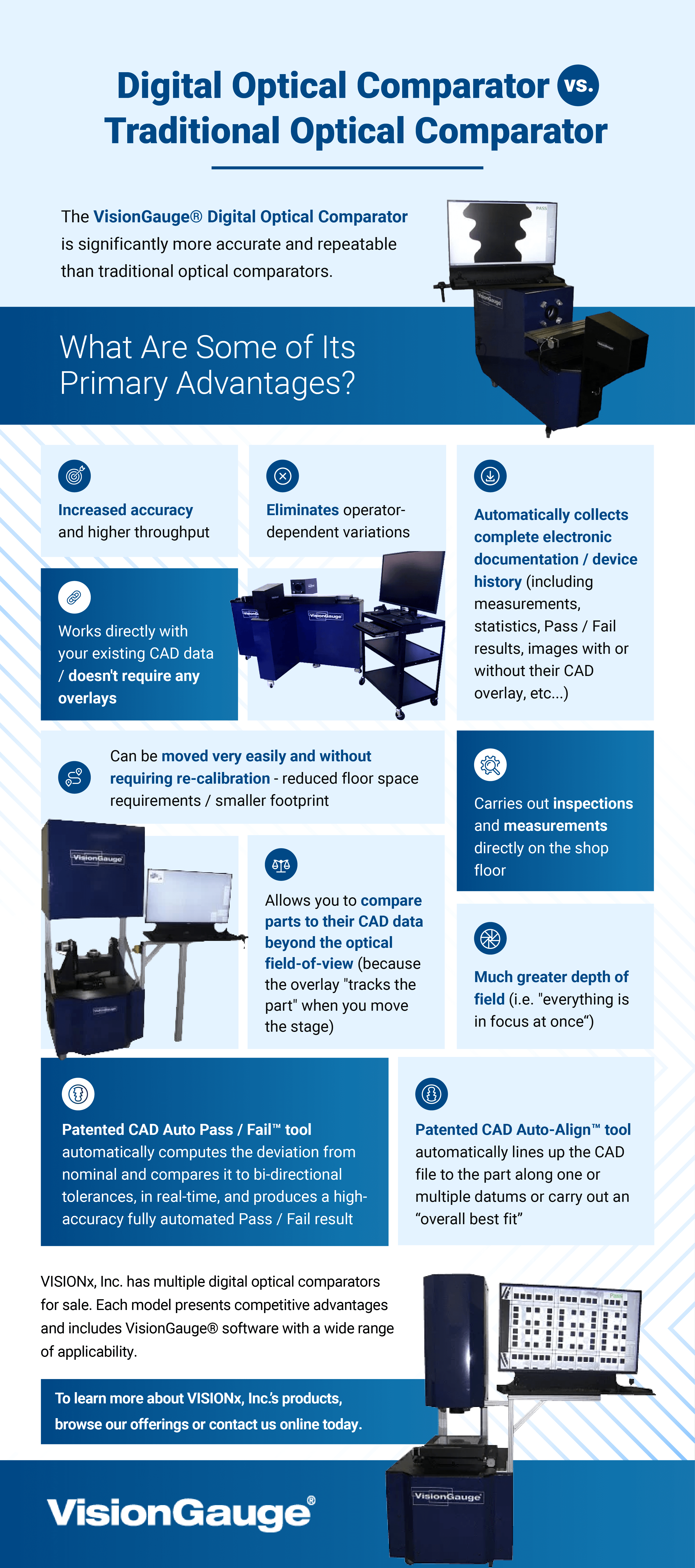
Both the manufacturer and users have performed real-word tests with the VisionGauge® Digital Optical Comparator, showing that it’s significantly more accurate and repeatable than traditional optical comparators. With VisionGauge®, measurement accuracy, repeatability, reproducibility, and Gage R&R results are much better. Below, we will look into the main reasons why the VisionGauge® Digital Optical Comparator offers complete measurement equipment accuracy.
1. Completely Different Optical System
Traditional optical comparators magnify a small portion of the part being inspected onto a large projection screen. Let’s consider, for example, a 10X, 30″ comparator. A 10X magnification means this comparator will project a 3″ portion of the part onto its 30″ projection screen.
A traditional optical comparator does this using an optical system that is comprised of prisms, lenses, and mirrors. These are difficult to manufacture, and all have a certain level of defects. The large lenses used in the lower magnification traditional optical comparators — such as 5X — are especially difficult to manufacture and are the ones that suffer from the most inaccuracies and non-uniformities.
The VisionGauge® Digital Optical Comparator works differently. If we stay with this 10X example, VisionGauge® takes this same 3″ field-of-view, but instead of “blowing it up” to 30″, it reduces it to a roughly 1″ camera sensor. Lenses that do this are much easier to manufacture and are more defect-free. This means that right out of the gate, VisionGauge® starts off with a much better, more geometrically accurate image.
Superior Contrast and Image Quality
This fundamental difference in the optical systems of traditional optical comparators and of the VisionGauge® Digital Optical Comparator brings about another important added benefit. It’s well known that traditional optical comparators have very low contrast, which makes it even more difficult for operators to determine — subjectively — if a part is within tolerance.
Historically, attempts to address this contrast issue have involved putting a screen or curtains around the operator’s station to try to “dim” ambient illumination and allow the operator’s eyes to adjust. This low contrast issue with traditional optical comparators is related to the fact that they take the light from the smaller area being inspected and disperse it over a much larger projection screen — in our example above, light from a 3″ area is dispersed over a 30″ area.
Since it uses a completely different approach with a completely different optical system, the VisionGauge® Digital Optical Comparator doesn’t have to deal with any of these contrast issues. Because it collects the light from a larger area onto a much smaller camera sensor, VisionGauge® isn’t light-starved like traditional optical comparators can be. With VisionGauge®, there are no contrast issues to overcome and the overall image quality is superior.
Larger Depth of Field
It’s interesting to note that VisionGauge®’s re-thought optical system also provides another benefit — a much larger depth-of-field. This means that in most cases, everything is in focus “at once,” and the operator doesn’t need to continually refocus as they do with traditional optical comparators that have a very thin depth-of-field. This doesn’t contribute to an increased accuracy per se, but it certainly is a benefit from the user’s practical perspective.
2. Mathematical Digital Image Correction
So far, we’ve seen why the image that reaches VisionGauge®’s camera sensor is much better and more geometrically accurate than the one that reaches a traditional optical comparator’s projection screen. But understanding how accurate a standard optical comparator is compared to a VisionGauge® Digital Optical Comparator doesn’t stop there.
At this point, VisionGauge® is working with a digital image. There’s much that can be done when the image is in digital form, especially in the case of a high-contrast, super-high-resolution digital image, such as the one produced by VisionGauge®. VisionGauge® takes this better, more geometrically accurate image and improves it further.
Specifically, VisionGauge® uses a proprietary calculation scheme to carry out real-time full 2D non-linear distortion correction – directly on the live image video stream. These corrections eliminate the last remaining small geometric inaccuracies in the image, which even further increases the system’s final precision and accuracy.
3. Digital Image Processing
VisionGauge® can carry out digital processing of the image, which is another advantage over traditional optical comparators. For example, VisionGauge® can apply edge sharpening, electronic noise reduction, or any of the digital image processing and enhancement techniques that are now so widespread via the various cameras prevalent in everyday life.
4. Works Directly With the Part’s CAD Data (No Overlays!)
Traditional optical comparators use templates, Mylars™, overlays, or transparencies to compare a part to its drawing. These are printed out on transparent material that is then laid on the comparator’s screen. Of course, no printer is perfect, and printing errors reduce accuracy. Over time, this overlay material can stretch and distort slightly, which leads to a further reduction in accuracy.
The VisionGauge® Digital Optical Comparator compares a part to its CAD data directly. The CAD data is the mathematical description of the part. The data to which VisionGauge® compares the part is completely error-free — with VisionGauge®, there are absolutely no inaccuracies introduced at this stage of the process.
5. Powerful Sub-Pixel Accurate Edge Detection
With traditional optical comparators, pass/fail determinations are subjective and operator-dependent: Multiple operators may need to consult each other for an opinion on if a part is good or bad. In comparison, the VisionGauge® Digital Optical Comparator uses sub-pixel accurate edge detection, making it ideal for high-precision manufacturing techniques. This completely eliminates operator subjectivity. Because its edge detection tool is sub-pixel accurate, VisionGauge® can actually locate edges accurately between pixels. This further increases digital optical comparator accuracy and precision.
6. Patented CAD Auto-Align™
With traditional optical comparators, the alignment of the overlay to the part and its datums are subjective. That can be a huge source of errors, and — obviously — results are operator-dependent.
The VisionGauge® Digital Optical Comparator has a powerful patented CAD Auto-Align™ tool that automatically aligns the CAD to the part along one or multiple datums or as an overall best fit. Results are extremely repeatable and completely operator-independent. This is a huge advantage over traditional optical comparators!
Furthermore, VisionGauge®’s CAD Auto-Align™ tool is not limited to the system’s field of view, or what the system “sees” at a given moment in time. It can actually travel down the length of long parts, capture images at different locations, and carry out a CAD Auto-Align™ over the entire length of the part. The automatic CAD-to-part alignment is not limited to small parts and can be carried out over large parts, to very high accuracy. That’s just about impossible to do on a traditional optical comparator, even in a subjective and operator-dependent fashion.
7. Patented CAD Auto-Pass/Fail™
Finally, with traditional optical comparators, the determination of whether or not a part is in tolerance is subjective, and again, results are operator-dependent.
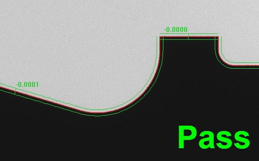
The VisionGauge® Digital Optical Comparator has a powerful patented CAD Auto-Pass/Fail™ tool that automatically determines if the part is within tolerance, either at point locations or across entire geometric entities. This provides much higher accuracy and completely eliminates operator subjectivity.
Additionally, VisionGauge®’s CAD Auto-Pass/Fail™ tool is also not limited to the system’s field of view. It can carry out a fully automated, high accuracy pass/fail determination over the entire length of the part, regardless of its size.
Summary of the VisionGauge® Digital Optical Comparator
The VisionGauge® Digital Optical Comparator is a drop-in replacement for traditional optical comparators that remains a general-purpose and easy-to-use system, capable of solving a wide range of inspection and measurement applications. These systems improve accuracy in manufacturing in general, including aerospace, medical, automotive, and a vast array of other industries.
Overall, the VisionGauge® Digital Optical Comparator represents a great technological leap forward from traditional optical comparators. It has innovative and up-to-date technology that, in many instances, completely does away with the inaccuracies that plague traditional optical comparators. As a result, the accuracy, precision, repeatability, and reproducibility of the VisionGauge® Digital Optical Comparator’s results are significantly better. Customer accuracy studies and Gage R&R studies have shown this time and time again.
Learn More About VisionGauge® Today
The VisionGauge® Digital Optical Comparator is your go-to choice for high measurement equipment accuracy. Contact us today to learn more about how our VisionGauge® systems can meet your needs for precision and accuracy in the manufacturing industry.
Also known as profile projectors, optical comparators are used in various industries to measure, analyze, and inspect manufactured parts and compare them to their design specifications. This process of comparing the existing part to its prescribed limits helps ensure parts fall within tolerance before use and that they are not overused or damaged. Comparators use lights, mirrors, and lenses to magnify a part and display the image on a screen for viewing.
Comparators can vary in a few ways, and the best type of optical comparator for your application will likely depend on your needs, including the parts themselves and your inspection requirements. Find out how to determine the best optical comparator with this guide.
Choosing the Right Type for Your Application
When choosing an optical comparator, you have some decisions to make regarding features that would best suit your application. Optical comparators can come in two configurations — vertical and horizontal — which is how the light shines on a part. In vertical optical comparators, the light shines vertically on the part so that the operator is looking down on it. In contrast, horizontal comparators provide a silhouette of the side of a part.
Both configurations can be used to inspect parts in various industries, ranging from manufacturing to aerospace. Ultimately, the configuration you choose will depend on the parts you’re inspecting.
Traditional vs. Digital
One of the biggest decisions to make is whether you’ll choose a traditional or digital comparator. Both types have their place in machinery inspection, though one is more efficient than the other.
The traditional optical comparator has had close to the same design since the birth of this technology in the 1920s. Traditional comparators require an operator to line a part up with a mylar overlay that serves as a guide for manual comparison. After aligning the overlay with the part, the operator determines whether the component can still be used if there are discrepancies. Overall, traditional comparators are fairly easy to use, though the manual process is slow and less accurate.
As technology advanced, comparators saw a digital shift. Digital optical comparators make the inspection process significantly more streamlined and precise. Instead of an operator taking measurements manually, parts are automatically compared directly with their CAD drawings to get a precise comparison. The automated process also can inspect multiple pieces at once, making the job much more effective.
Because digital comparators allow operators to inspect multiple parts simultaneously, they’re typically a more efficient option for applications requiring regular inspection of many parts. Both types of comparators have their worth in certain applications, and the best optical comparator for you will depend on your industry’s demands.
Accuracy
As machinery becomes more advanced and parts become more specific, the need for more accurate inspections and comparisons increases. The more complex machine parts become, the harder it becomes to complete accurate comparisons with a traditional comparator. In some cases, manual comparisons cannot reach the necessary level of accuracy. In these applications, a digital comparator is often required to ensure the most accurate comparison.
While traditional comparators can still be accurate, there is also a risk of human error. Without highly trained comparator operators, some companies are likely better off with the automated accuracy of a digital comparator.
Optical Comparator Accessories and Characteristics
While traditional and digital comparators are used for many of the same jobs, some differences in their characteristics may help you decide which is best for your application. Let’s look more closely at some defining characteristics of optical comparators of each type.
One of the most significant traits of traditional optical comparators is the need for physical overlays. Most commonly made of mylar, overlays are printed with CAD charts, grids, angles and more. Overlays serve as a comparison guide for the operator, allowing them to take measurements of parts. The comparator only projects 2D images of elements, limiting the operator to inspecting less complex components in one view.
Traditional comparators also require time-intensive manual labor. These comparators only measure parts one at a time, which can be incredibly time-consuming. They typically only come with one magnification, though additional lenses can be purchased.
Digital optical comparators typically offer a lot more. They provide automated rotation for views of parts in multiple lighting modes. Because they are automated, they rely on software and cameras to quickly and precisely analyze parts. This feature allows these comparators to automatically analyze several parts at once without help from a human operator.
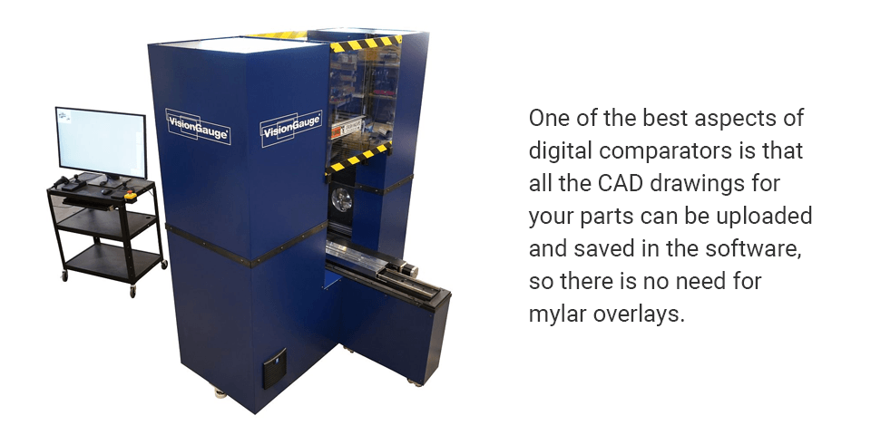
One of the best aspects of digital comparators is that all the CAD drawings for your parts can be uploaded and saved in the software, so there is no need for mylar overlays. The software also allows you to save and store analysis reports and documentation, keeping everything in one place.
Choosing a Reliable Manufacturer
Another important aspect of finding the best optical comparator is choosing a reliable manufacturer. A reliable comparator manufacturer will consistently work to improve their products. Whether it’s timely updates to the software, remote support when a problem arises, or application support to start inspecting a new part, be sure you’re purchasing an optical comparator from a manufacturer that will support you after your purchase.
Technical Support
A reliable manufacturer will provide remote technical support. Support from anywhere in the world lets you contact the company if you’re having an issue with their product. They may ask you to walk them through the problem over the phone or even access your system remotely to explore and solve the issue themselves. Make sure you choose a comparator from a manufacturer that will take the time to help you get back to the task at hand without major downtime.
Application Support
Application support involves training and support related to using the product effectively for a given function. Reliable manufacturers want to ensure their customers know how to use their products in any field where the solution is being applied. Comparator manufacturers that offer their products to various industries should understand how the comparator works within each sector to help with setup and training for new users so they can confidently solve their applications.
Use the VisionGauge® Digital Optical Comparator for Your Inspections
We specialize in optical solutions that provide high-accuracy measurements. All of our systems and products are powerful and easy to implement, and you can find our devices in labs, production floors, and industrial facilities around the world. We’re dedicated to providing prompt support alongside our products so you can use them effectively.
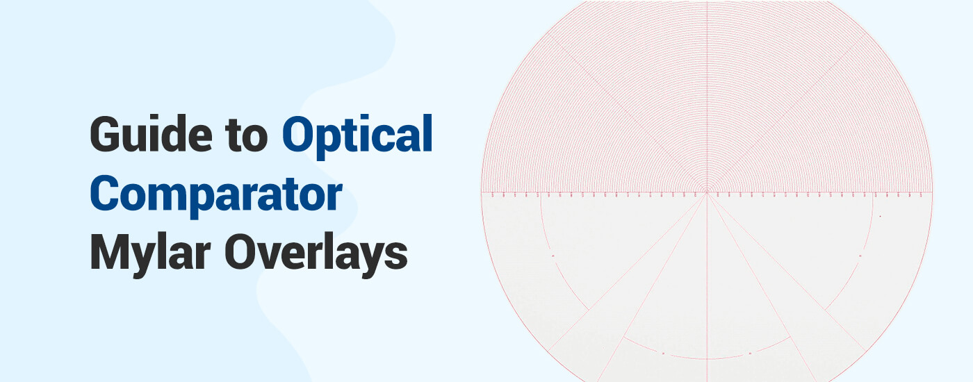
The modern manufacturing industry relies heavily on optical inspection to verify parts are meeting compliance standards. This procedure uses optical comparator technology to compare a part to its computer-aided design (CAD) file. Optical comparators have been around since the 1920s, and the modern units’ operations are still similar. However, as technology advances, the need for physical optical comparator mylar overlays is diminishing.
This guide will explain why mylar overlays are essential to traditional optical comparators, and how digital optical comparators are eliminating the need for mylar overlay charts.
The Role of Mylar Overlays With Optical Comparators
Mylar overlays are transparent charts that are used to manually compare a machine’s part with its CAD drawing. Overlays serve as a guide for comparison. They help the optical comparator operators take measurements of a given part and determine if the part’s critical dimensions are within specifications or if the part has sustained any damage and should be replaced.
An operator turns on the optical comparator and places the desired part in the staging area to be observed.
Once the image is displayed, the operator places the corresponding overlay on the screen and physically aligns it with the projected image of the part.
Finally, the operator manually compares the CAD drawing on the overlay to the part’s image. If there are any discrepancies identified in the part, the operator has to determine if it is still within tolerance to operate safely.
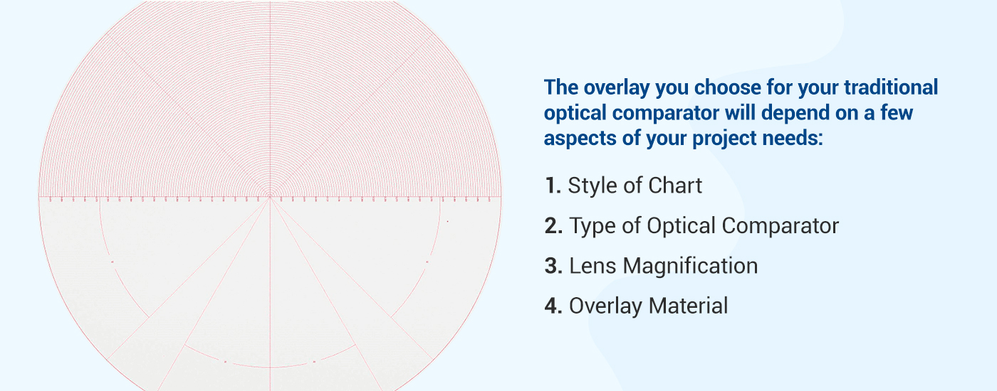
How to Choose a Mylar Overlay
The overlay you choose for your traditional optical comparator will depend on a few aspects of your project needs:
1. Style of Chart
In addition to mylar overlays with CAD charts on them, overlays can be printed with different grids or angle measurements. These overlays are used to take precise measurements of a part’s radius or angles. These other styles of overlay charts can be as simple as a four-quadrant grid or as complex as charts for checking a screw’s thread forms. Other charts can be printed with 360-degree protractor lines or angle measurements of your choice — or even a combination of the two.
2. Type of Optical Comparator
When ordering an overlay, you’ll want to specify what model and type of comparator you’ll use the overlay with. Some optical comparators are compatible with specific materials, overlay sizes, or thicknesses.
3. Lens Magnification
It’s essential to consider the magnification you’ll be viewing the images or CAD files at. If the overlay is printed with the wrong magnification in mind, the operator will be unable to take accurate measurements or make an accurate assessment of a part. The magnification scale can also vary depending on the machine, the overlay manufacturer, and the material used.
4. Overlay Material
Overlays can be made of various materials. The most common material is a mylar sheet. Overlays can also be made with plastic or vinyl. Different materials will have different thicknesses, which could affect how the overlay works with the optical comparator. It’s also common for overlays to have either a frosted or clear finish, affecting the visibility of a chart on the projector.
Digital Optical Comparators
Digital optical comparators are becoming increasingly popular and necessary as machinery gets more advanced. Digital comparators are far more efficient because they eliminate the need for mylar overlays.
Traditional mylar overlays are easily damaged, especially when handled frequently. Because of the sheer number of overlays needed for each piece of machinery, storage for the overlays requires a significant amount of space. This also means that if an overlay is misfiled, locating it can be time-consuming, which delays the inspection process. Mylar overlays are expensive to make, and when product designs change, the cost of replacements can add up quickly.
A digital optical comparator uses digital CAD charts and an internal projector to display a part’s image. The virtual charts can automatically adjust to changes in magnification — an operation that would normally require the overlays to be physically changed. Also, digital CAD charts can be automatically aligned on a part, automatically compare the part to the overlay, and can stay aligned as a part moves by automatically tracking/moving with the part. Since the digital CAD charts are used directly, when designs change, there’s no need to make a new mylar overlay. CAD files can be limitlessly imported and easily accessed and stored on a secure network, making the automatic part comparisons that much faster.
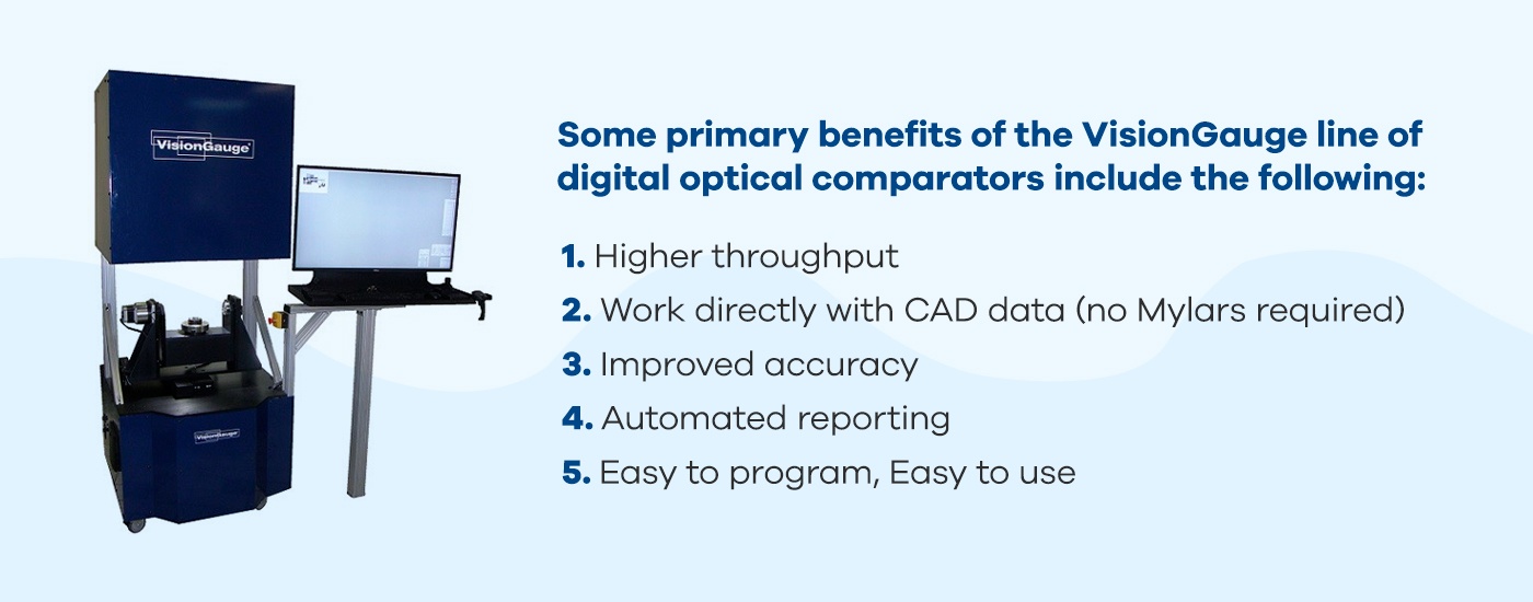
Digital Optical Comparator Benefits
Digital optical comparators, like the VisionGauge® Digital Optical Comparator, can benefit many manufacturing industries, including medical and orthopedic, automotive, biomedical, electronics, telecommunications, power and energy, and more. Some essential benefits include simplified use, improved accuracy, and full automation:
1. Simplified Use
If you thought traditional comparators were easy to operate, digital optical comparators are incredibly simple to use in comparison. The operator only has to complete one step — position the part on the staging area. The digital optical comparator’s advanced software takes care of the rest. Digital comparators work directly with CAD files, which eliminates the need for tedious overlays or templates. Without the need for overlays, the process becomes simple and automated.
2. Improved Accuracy
Because they are digital, these optical comparators are exceedingly accurate. The automation of the digital optical comparator functions eliminates the potential for human error when taking detailed measurements. Digital comparators are also equipped with software that provides detailed documentation of statistics, measurements, and a record of pass/fail results. This information is then safely stored on a secure network.
3. Fully Automated
One of the most significant benefits of digital comparators is that they are fully automated. Using fast software and cameras, digital optical comparators analyze and measure parts automatically. Within seconds, the system aligns the part with its CAD drawing and compares the two. The automatic functions allow operators to increase throughput with fast comparisons.
4. Additional Benefits
More benefits of the VisionGauge® Digital Optical Comparators include:
Eliminate the need for optical comparator overlay charts
Highly reliable
Support for automated rotation for multiple views of the same part
Automatically analyze multiple parts
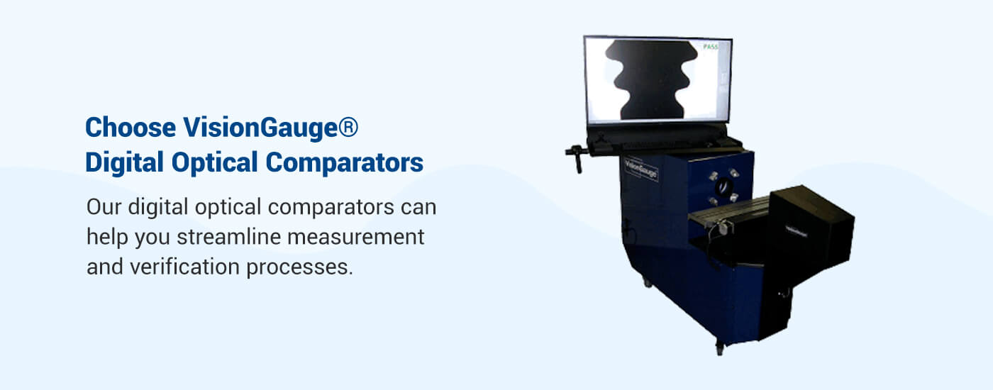
Choose VisionGauge® Digital Optical Comparators
At VISIONx, Inc., our goal is to help your company’s inspection process become accurate, fast, and effective. VisionGauge® Digital Optical Comparators can help you streamline measurement and verification processes so your employees can quickly complete more tasks with high accuracy and reliability. Our operator-independent technology allows for a wide range of automatic results.
In addition to our state-of-the-art digital optical comparators, we also develop, sell, and support software, hardware, and other systems for all your inspection, measurement, and imaging needs. No matter what industry you’re in, you can rely on VISIONx, Inc. for standard or custom solutions. Browse our available products or contact us for more information today.
The optical comparator (profile projector) has been used in quality control in the manufacturing industry since it was first patented in 1925. The overall design has changed little in that time, with the exception of some digital and software enhancements. The continuing popularity of this device is a statement of how useful it is for optically checking parts for conformance and deformities.
Here we will discuss what comparators are, as well as the following questions: what is an optical comparator used for, how does it work, and how do traditional models compare to digital ones?
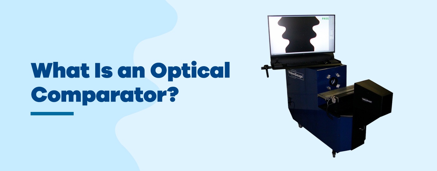
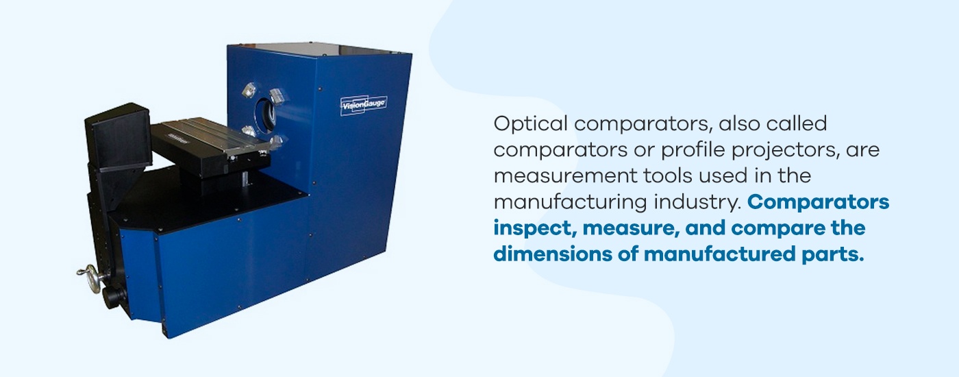
Optical comparators, also called comparators or profile projectors, are measurement tools used in the manufacturing industry. Comparators inspect, measure, and compare the dimensions of manufactured parts. These measurement tools function using the principles of optics by utilizing illumination, lenses, and mirrors to project a magnified silhouette of a part upon a screen. Doing this compares the part to its prescribed limits.
Optical comparators are used to check for both dimensional accuracy and surface defects, such as scratches and indentations. In short, they allow for non-contact measurement and observation, minimizing handling while still allowing for close inspection.
Horizontal comparators: In a horizontal model, the optical comparator’s light travels horizontally so the viewer is looking at a silhouette taken from the side of a part. This model works best for parts held in a fixed location — some examples include screws that are fixed in place or castings that must be held in a vise.
Vertical comparators: In a vertical model, the optical comparator’s light travels vertically so the viewer is looking down on the part. This works best for flat components that can lie on the work stage, such as gaskets. They also work well on flexible or soft elements that need to lie on a flat surface to provide an accurate measurement.
Optical comparators of both types can be found in manufacturing shops and lab environments related to quality control. They are most popular in industrial sectors, including the scientific, automotive, medical manufacturing, aerospace, and defense industries.
How Does an Optical Comparator Work?
Optical comparators have changed little since they were invented in the 1920s — the reason for this is that the technology uses optics, which have only changed in quality, not function. Optical profile projectors work similarly to overhead projectors commonly used in classrooms. A light is directed through a stage to a series of lenses and mirrors, which then project the silhouette of whatever is on the stage onto a screen.
Optical comparators use this same principle. A part is affixed to a stage and a light source shines on it, resulting in a shadow image of the part. The shadow is magnified with lenses and bounced by mirrors onto the back of a screen. This screen is fixed at a known distance for measurement purposes.
Optical comparators can vary in the size and magnification of the projected image. Both of these metrics depend on the optics and screen size of the comparator. Screen sizes for optical comparators range from 12 to 36 inches, though models with larger screens are available. However, larger screen sizes are only possible with larger enclosures, as a greater distance is required to generate a bigger image without distortion.
Another way that optical comparators differ is in the measuring processes they use. There are three different measuring processes for comparators:
Silhouette measurement: The simplest measurement method is to project a silhouette of the image onto a screen for measuring. Because the magnification is known, the silhouette can be used to gain accurate measurements.
Point comparison: The second measurement method is to compare the image’s silhouette to prescribed plan points on a screen. The part’s silhouette is centered on the screen and the user moves the stage to hit various points on the screen. This measures how much the stage had to move to match the part to the point.
Software analysis: The last measuring process is digital, using software to analyze and measure the image generated by the optical comparator.
The first two methods are used by traditional optical comparators and are the most common in the industry. The third is employed by digital optical comparators, which handle the entire process electronically.
How to Use a Traditional Optical Comparator
Using an optical comparator with a traditional setup, the steps are similarly simple:
Placement: First, the operator must turn on the optical comparator and place the part to be observed on the staging area.
Alignment: When the part’s image is projected on the comparator’s screen, the operator must place an overlay on the screen. The overlay, also known as a template or Mylar, is a part drawing printed on a transparent overlay that is scaled to match the magnification of the comparator. The operator must align this overlay with the part’s image.
Comparison: Once the overlay is placed, the operator compares the drawing to the image and identifies any discrepancies. From these discrepancies, the operator will determine if the part is within tolerance.
This is the process used for most traditional optical comparators, though there are various methods available for this technology. For example, instead of an overlay with a part plan, an overlay may feature a grid or concentric circles to allow for more precise measurements of a part. Alternatively, a point comparison method may be used, where the image’s silhouette is centered on the screen compared to an overlay. The user then moves the stage to hit prescribed points on the overlay, measuring how much the stage had to move to match the part to each point.
Limitations of Traditional Optical Comparators
Profile projectors are generally straightforward and require little training to use. Traditional optical comparators that use silhouette measurement or point comparison simply require the user to fix a part in place and observe the on-screen image.
While traditional optical comparators are easy to use and operate, they also present disadvantages because of their simplicity. Some primary flaws of traditional optical comparators include the following:
Limited complexity required: Production parts are becoming more complex, and observing them at more than one angle is becoming increasingly necessary. However, traditional comparators don’t accommodate this well.
Less accurate: How accurate is an optical comparator? Although traditional optical comparators can obtain very accurate measurements, today’s modern parts require tighter tolerances, reducing the room for error that is allowedwith any manual measurement method.
Labor intensive: Traditional optical comparators can only measure one part at a time. This poses a problem when needing to inspect large quantities of parts, as is often needed in the manufacturing industry. This is particularly the case when inspecting large quantities of parts at once, since a vision system can allow you to place multiple parts for inspection on the stage at the same time.
2D limitations: Traditional optical comparators can only project 2D images onto a screen, which can present issues for analyzing multiple dimensions at once.
Although these limitations present no issues for non-repetitive tasks used to analyze 2D parts, anything outside of this defined operating bubble is an obstacle for traditional optical comparators. For large-scale, complex analysis, a different model is necessary.
Digital Optical Comparators vs. Traditional Optical Comparators
Where traditional optical profile projectors fall short, digital models pick up the slack. Manual comparator technology is highly useful in small-quantity applications, but with the rise of more complex parts and large-scale manufacturing, automation is necessary. Digital optical comparators present the solution.
Digital optical comparators offer the following advantages:
Automation capabilities: These models use software and cameras instead of human eyes to analyze and measure parts. The software automates the measuring process and completes it more quickly than a human can.
3D capabilities: Digital optical comparators can use multiple lighting techniques and 3D inspection methods to analyze parts in all three dimensions.
Quantity management: The automated nature of digital optical comparators means they can analyze multiple parts automatically without human intervention.
Accuracy: By removing the potential for human error, digital optical comparators are extremely accurate in their measurements, which is necessary for many modern industries and technologies.
These advantages effectively maximize the accuracy of optical comparator measurements while reducing labor.
Using Traditional Optical Comparators vs. Using Digital Optical Comparators
While traditional optical comparators are generally straightforward to use, they present significant disadvantages to both users and clients. Some of the most significant drawbacks include:
Little quantifiable data: Measurements using traditional comparator methods can be subjective and difficult to quantify. When comparing a part to an overlay with a plan, the goal is simply to pass or fail the part. However, clients are increasingly asking for quantifiable data about each deviation, which is difficult to achieve with this method.
Limited flexibility: Traditional optical comparators only project 2D images onto a screen. This presents an issue in an industry where parts are becoming increasingly complex and require analysis from multiple angles. With a traditional optical comparator, an operator analyzing a complex part must physically move the part and utilize multiple overlays for analysis, which can be difficult depending on the part’s geometry and requires a significant input of time and labor.
Reduced accuracy: Today’s parts require tighter tolerances and more quantifiable data. Although traditional optical comparators are capable of gathering accurate measurements, this requires a highly trained operator. Additionally, the manual nature of a traditional optical comparator always leaves room for human error.
High costs: Traditional optical comparators incur significant costs over time. Overlays are expensive to produce, and the labor input required for traditional optical comparators is significant, especially for complex parts.
In short, traditional optical comparators require extensive training to use properly and need significant labor input. While these limitations may be a non-issue for small operations that work with simple parts, the manufacturing industry as a whole is quickly growing in scale and complexity. It needs optical comparator tools that can keep up.
Manufacturing companies need tools that are quick and easy to use to handle large quantities of complex parts. This is where digital optical comparators come into play. Digital optical comparators take the concept of traditional optical comparators and apply new technology to key areas. The result is an automated technology that is faster and easier to use, reducing the labor input of operators.
How to Use a Digital Optical Comparator
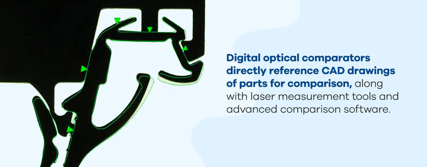
Digital optical comparators pick up the slack where traditional models fall short. Digital optical comparators, like traditional models, utilize optics for comparing a part to its plans. However, digital optical comparators do so by augmenting the existing comparator technology with a combination of measurement and analysis tools. Digital optical comparators directly reference CAD drawings of parts for comparison, along with laser measurement tools and advanced comparison software.
So what does this mean for operators? Essentially, digital optical comparator instructions for operators are pared down from three steps to one: place the part on the staging area. From there, the digital optical comparator does the rest. The system will automatically handle alignment and comparison, providing a pass/fail result along with analytical data supporting the decision.
In addition to the simplified use, digital optical comparators also offer the following advantages:
Fast automation: Digital comparators use software and cameras to analyze and measure parts automatically. The system automatically aligns and compares parts with their CAD drawings, doing so within seconds. This minimizes operator input and allows for higher throughput.
3D capability: Digital optical comparators use multiple lighting techniques, additional positioning stages (e.g. rotary stages), and lasers to analyze parts in all dimensions, allowing for quick, one-shot measurements with minimal operator interference.
Improved accuracy: Digital optical comparators are extremely accurate, accomplishing highly detailed measurements automatically and eliminating the potential for human error. Additionally, the digital comparator software provides detailed documentation backed with thorough data, including measurements, statistics, and pass/fail results for parts and batches.
While automation is one of the many significant benefits to using the VisionGauge® Digital Optical Comparator, the system is also accurate and efficient when used manually by an operator wanting to perform direct measurements on a part or make manual comparisons of a part to its CAD file. The VisionGauge® software interface is intuitive and easy-to-use even for manual operation: Operators can quickly load part CAD files and pre-programmed inspection routines with the system’s barcode reader, and the stages and overlay can be manually controlled with the system’s industrial-grade joysticks. Both automated and manual operation modes produce highly accurate results and complete documentation.
Applications of Digital Optical Comparators
Companies across a range of industries use digital optical comparators to solve various applications. Below are some common digital optical comparator uses and applications:
Aerospace: Aerospace manufacturers use optical comparators to inspect and measure turbine disks and slots, cooling holes, turbine blade fir trees, seal slots, and slots on five-axis parts. Digital optical comparators improve accuracy and repeatability, increase throughput, and collect electronic documentation – all essential functions in the aerospace industry.
Automotive: In the automotive industry, digital optical comparators inspect flexible auto seals and trim, measure, and inspect various components and parts. Digital optical comparators are ideal for comparing seals against CAD data, especially when the components are difficult to inspect.
Bearings: Accuracy in manufacturing is critical for precision bearings. A digital optical comparator checks bearings on the shop floor and works much faster and more efficiently than traditional methods.
Machining: Digital optical comparators include tools designed to check machining parts. The patent pending VisionGauge® Tooth Checker inspects screw teeth.
Medical devices: Multiple tools are available for inspecting and measuring medical devices and implants with digital optical comparators. For example, the VisionGauge® Tooth Checker tool can examine implant screws. Optical comparators can also inspect stents, medical rasps, orthopedic implants, and more.
Defense/military: Equipment used for military and defense purposes also benefits from inspection by a digital optical comparator. VisionGauge® can efficiently automate inspecting parts with large numbers of holes or other features and works much faster than other systems.
Power and energy: Micro-hole inspection also has applications in the power and energy industry. Additionally, cooling hole inspection and measurement tools measure the location of laser-drilled and electrical discharge matching (EDM) holes.
Tool and dye: Digital optical comparators are ideal for use when you need to inspect thread rolling dies. You can set the system to automatically identify and check features based on your specifications.
Digital optical comparators have many applications in addition to those listed above.
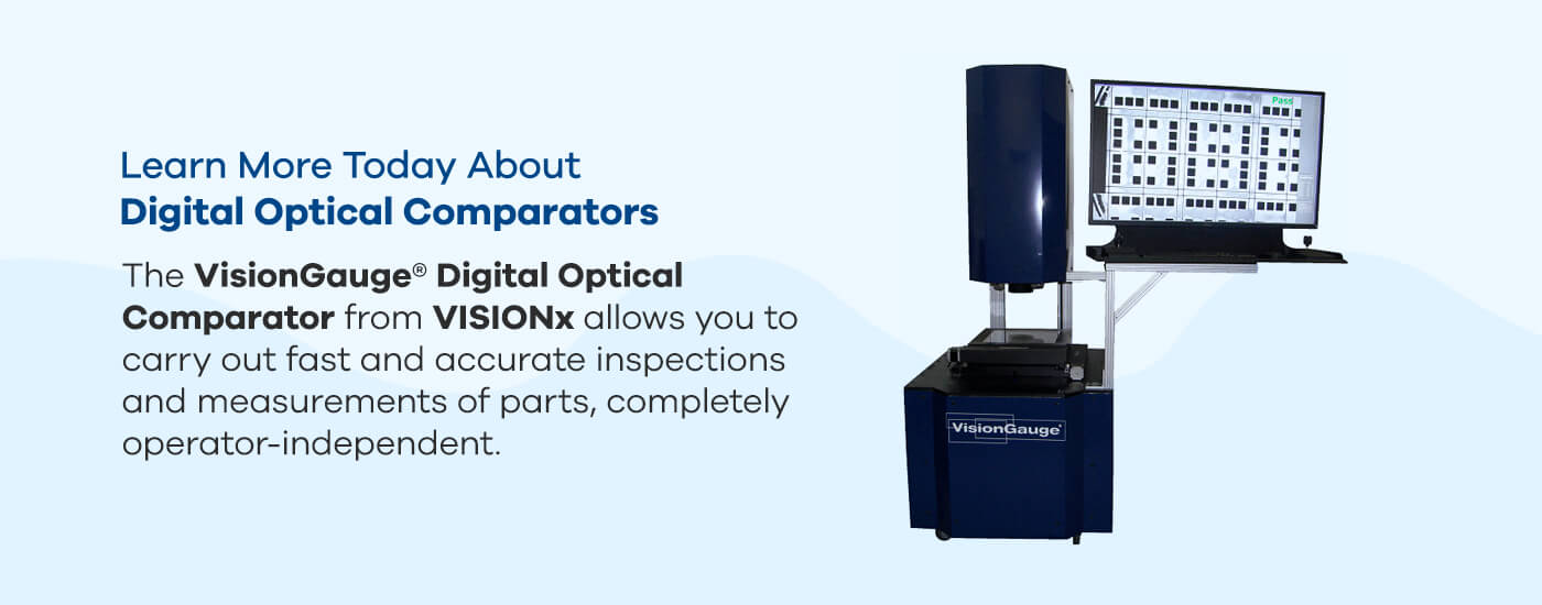
Learn More Today About Digital Optical Comparators
Using an optical comparator doesn’t need to require extensive training or massive labor inputs. Simplify your optical inspection with VISIONx, Inc’s VisionGauge® Digital Optical Comparator. Our digital optical comparator is an advanced optical analysis tool that maximizes the function of optical comparator technology. They are extremely precise yet easy to use, delivering fast, high-quality results. They allow you to carry out fast and accurate inspections and measurements of parts, completely operator-independent.
VISIONx, Inc. has multiple optical comparators for sale. Each model presents competitive advantages and includes VisionGauge® software with a wide range of applicability. On top of our optical comparators, VISIONx, Inc. develops, sells, and supports software, systems, and hardware for other automated imaging, visual inspection, and measurement solutions. With powerful and easy-to-use products, you can rely on VISIONx, Inc. for custom or standard solutions in various industries — from aerospace and automotive to electronic and medical device manufacturing.
To learn more about VISIONx, Inc.’s products, browse through our list of offerings or contact us online today.


 Learn More Today About Digital Optical Comparators